

 Richard
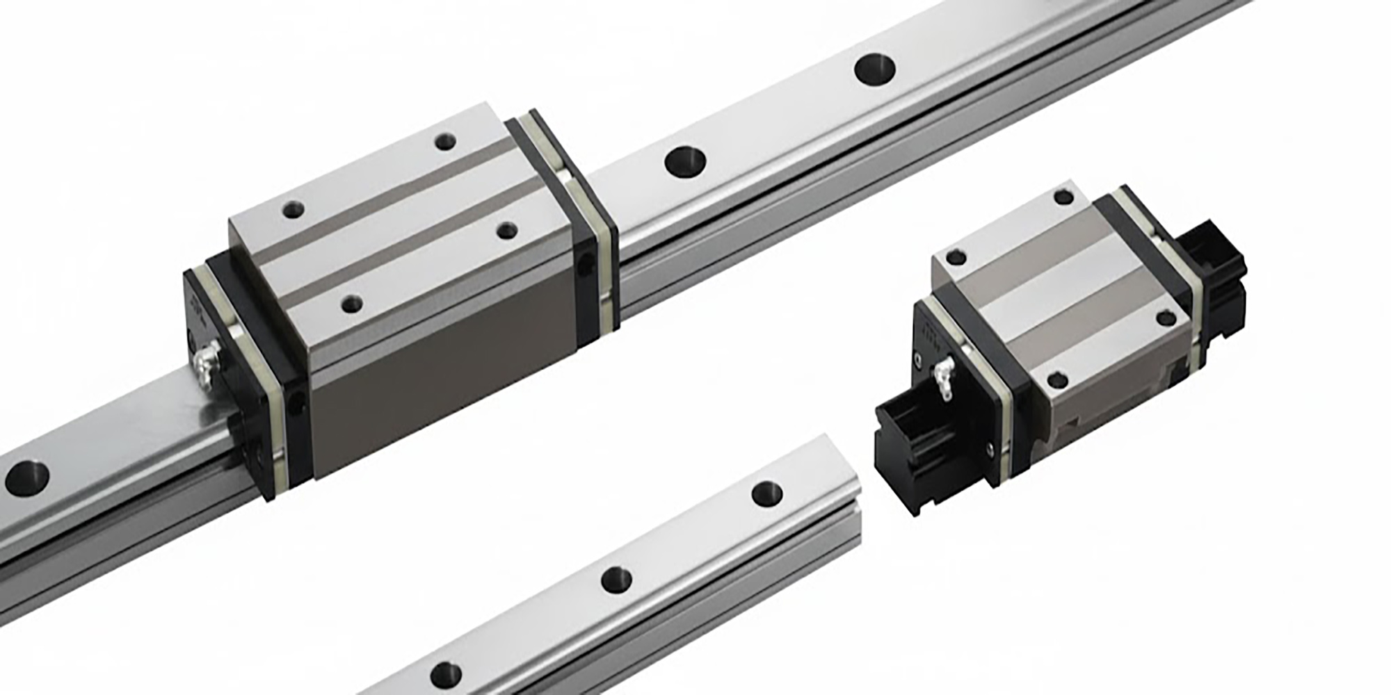
Beyond the Rail: How to Choose the Right Linear Guide for Any Precision Application
What Is a Linear Guide? A linear guide is a mechanical component. It is also known as a linear motion guide or linear guideway. It is made to...
Press fit is one of those fundamentals that shows up in nearly every rotating machine — from the wheel bearing on your car to the spindle in an industrial pump.
And yet engineers still get it wrong.
A bearing installed with too loose a fit spins in its housing and destroys the bore within weeks.
One pressed in too tight cracks the outer ring on the first startup.
Tolerance values are taken from ISO 286-1:2010.
Installation guidance is aligned with published bearing manufacturer specifications.
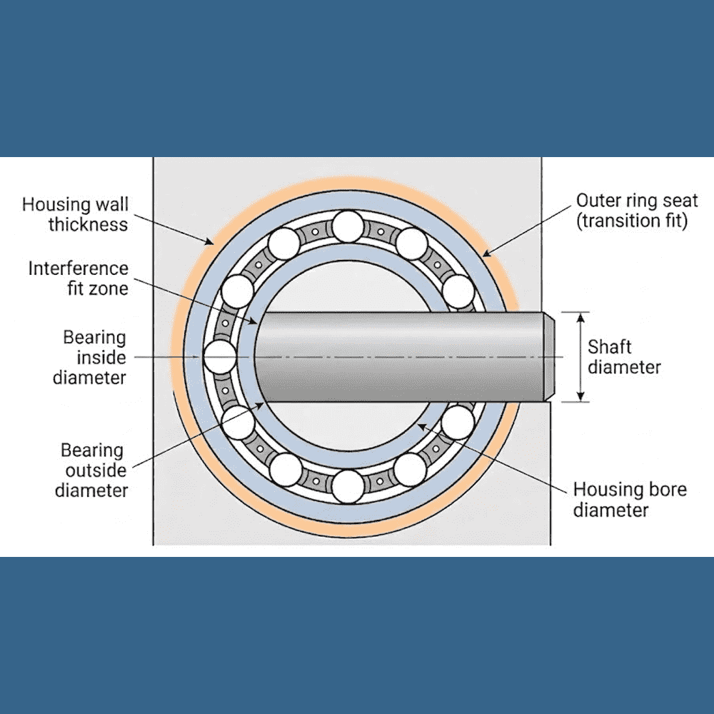
A press fit — also called an interference fit — is a joint where the shaft is intentionally made slightly larger than the hole it goes into.
That size difference is called the interference.
When assembled, the material deforms elastically, creating a clamped connection held entirely by friction.
No fasteners. No adhesive.
Interference is simply the difference between the two diameters before assembly:
Interference = Shaft diameter − Bore diameter
For a steel-on-steel assembly under normal industrial loads, a typical interference is 0.025 mm to 0.075 mm (0.001" to 0.003") for a 25 mm shaft.
That's less than the width of a human hair — but it's enough to resist thousands of newtons of axial and radial force.
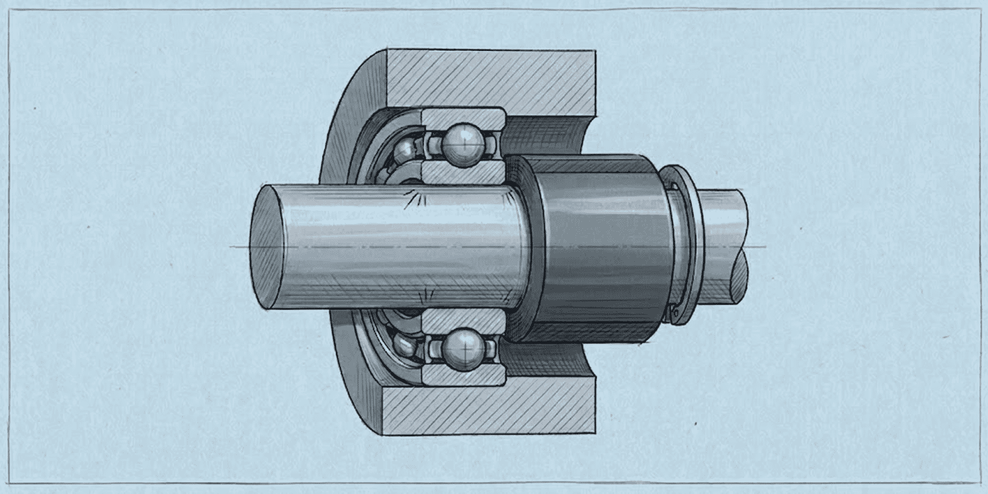
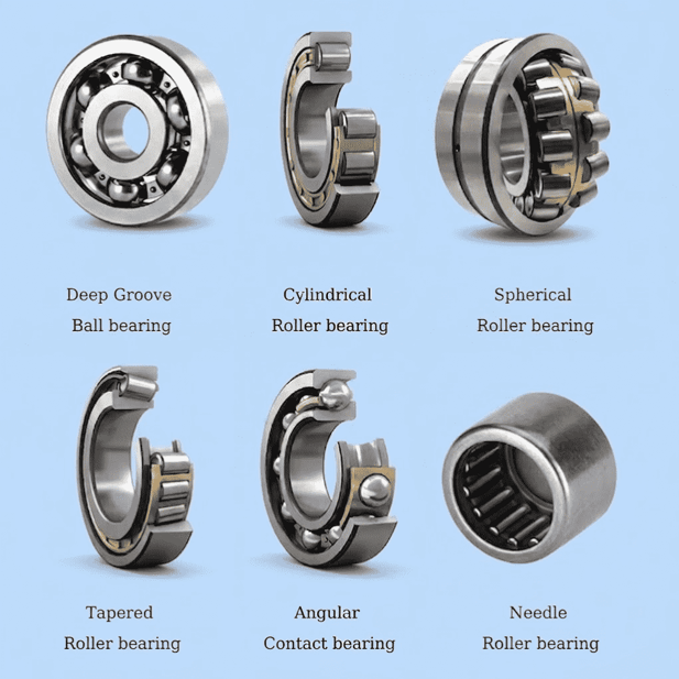
Bearings almost always use an interference fit on at least one ring — and that choice is deliberate, not arbitrary.
Press fit is not always the right answer — it depends on which ring rotates.
The rotating ring must have an interference fit to prevent creep.
The stationary ring can use a slip fit (clearance fit), and in many cases should: it allows dismounting without a puller, accommodates thermal expansion in the housing, and in some designs permits intentional axial float.
A slip fit on a stationary ring is a deliberate engineering choice.
A slip fit on a rotating ring is an application error — even under light loads, creep will develop. It just takes longer.
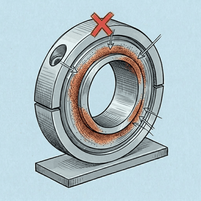
A bearing that can move in its seat will fail early.
The failure mode is called creep — the ring rotates slightly within its housing or on its shaft due to cyclic loading or vibration.
The result is fretting corrosion: that familiar orange-brown powder that erodes the contact surface.
Once creep begins, it accelerates. The bore grows.
The interference disappears entirely.
A correctly installed pressfit bearing eliminates creep by locking the ring in place.
Load transfers through the interference joint itself, keeping the contact geometry exactly where the bearing designer intended.
The rule: the rotating ring always gets the interference fit. The stationary ring gets a looser fit so it can be removed for service.
Exception: if both rings rotate relative to the load direction which occurs in certain planetary gearbox designs — both rings require interference fits. Check the bearing manufacturer's application guide.
No — but most rotating applications do.
Whether a pressfit bearing is required depends on which ring rotates relative to the load direction.
In practice, deep groove ball bearings in electric motors almost universally use an m5 or k5 shaft tolerance.
Pillow block units — the self-contained housings common in conveyor and agricultural equipment — often use a taper lock or adapter sleeve instead of a direct interference fit.
That's a legitimate exception, not a shortcut.
Tolerance selection follows ISO 286-1:2010, the international standard for limits and fits.
Each tolerance designation combines a letter (the position of the tolerance band relative to nominal zero) and a number (the IT grade, which sets the tolerance width).
For a rotating inner ring on a shaft, the standard interference tolerances are:
These values are for a 25 mm nominal diameter per ISO 286-1.
Interference increases with shaft diameter — always use the bearing manufacturer's mounting tolerance tables for your actual bore size, as the bands shift substantially above 50 mm.
For a stationary outer ring in a housing bore:
Pressing a pressfit bearing onto a shaft reduces its internal clearance — and most engineers don't account for this.
The inner ring expands under the interference force, closing the gap between the races and rolling elements.
As a rule of thumb, approximately 80% of the shaft interference translates into a reduction in radial internal clearance (this is an approximation — the actual proportion depends on ring geometry and material).
So a 0.030 mm interference on a 25 mm shaft reduces internal clearance by roughly 0.024 mm.
If you've specified C3 (extra clearance) bearings to handle high operating temperatures, account for this reduction when selecting the clearance group — otherwise the bearing may run with unexpected preload.
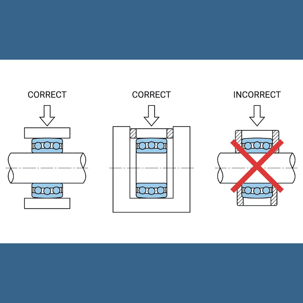
Incorrect installation is the leading cause of premature bearing failure.
A bearing struck on its rolling elements — rather than on the ring face — can sustain raceway damage that isn't visible externally but will cause failure within a fraction of the calculated service life.
Best suited to smaller bearings with low interference (typically up to approximately 0.05 mm), using an arbor press or hydraulic press.
For larger bearings or higher interference values, heating the bearing expands the inner ring enough that it slides onto the shaft without pressing force.
This is gentler on the bearing and far less likely to cause damage.
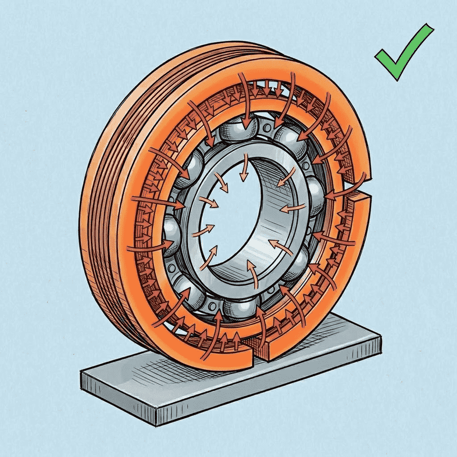
Induction heaters are the preferred tool in production environments — 3 to 5 minutes to target temperature, precise cutoff control, and no risk of oil contamination or fire.
Self-aligning ball bearings and spherical roller bearings are often available with tapered bores (1:12 or 1:30 taper).
These mount on a tapered adapter sleeve rather than directly on the shaft.
A hydraulic nut threads onto the sleeve and applies controlled axial force to push the bearing up the taper.
Interference is determined by axial drive-up distance, not by shaft/bore diameters.
The bearing manufacturer's table gives the required drive-up in millimeters for each bearing size — for example, a 22216 spherical roller bearing (80 mm bore) on a 1:12 taper requires a drive-up of approximately 0.90–1.25 mm from the zero-clearance position.
This method is especially valuable in conveyor and heavy industrial applications because bearings can be dismounted and remounted without damaging the shaft, and interference is set consistently by measurement rather than feel.
A two-jaw or three-jaw bearing puller is the standard tool for extracting bearings from shafts.
The jaws grip behind the inner ring face — not the outer ring, and never the cage or rolling elements.
The center bolt bears against the shaft end and applies steady axial extraction force as you tighten it.
A few things to get right: position the jaws as close to the ring face as possible to minimize bending stress on the jaws.
Apply force slowly — a sharp impact can transfer shock load through the rolling elements and Brinell the raceways of a bearing that was otherwise serviceable.
If the bearing is extremely tight, consider a hydraulic-assist puller — it replaces the center bolt with a hydraulic ram, giving more controlled force and eliminating the risk of slipping jaws.
Always pull on the ring that has the interference fit.
Pulling on the outer ring to extract a bearing from a shaft loads the rolling elements in an unintended direction and will damage them.
For bearings seated in housings — or wherever a puller can't get purchase — a hydraulic press with a correctly sized sleeve is the cleanest option.
Support the housing or shaft firmly so the load path goes directly through the sleeve to the ring being removed.
The sleeve must contact only the ring face being extracted — not the shaft, rolling elements, or cage.
A set of graduated bearing installation/removal sleeves covers most common bore sizes and is one of the more useful investments for a maintenance shop.
Apply press force slowly and steadily.
If the bearing doesn't move within the first 2–3 mm of press travel, stop and check alignment.
Applying full press force to a cocked bearing can crack the housing or the ring.
Dry ice (−78°C / −109°F) contracts a steel shaft by approximately 0.030 mm per 25 mm of diameter per 100°C of temperature drop (steel linear expansion coefficient: 12 × 10−6/°C).
For a 50 mm shaft cooled from 20°C to −78°C (a drop of ~100°C), that's roughly 0.060 mm of diameter reduction — enough to meaningfully reduce a light to moderate interference fit.
Pack dry ice around the shaft for 10–15 minutes while keeping the bearing housing at room temperature (or gently warming it).
The differential expansion reduces the interference, and the bearing can often be driven off with moderate force rather than a press.
This approach is most practical when the bearing is in a location that a puller or press can't easily reach, or when protecting a precision shaft surface is the priority.
Combine with light heat applied to the bearing outer ring for maximum effect — but keep the heat below 100°C to avoid affecting the ring's heat treatment.
Note: Don't use a cutting tool to remove a bearing you intend to keep. And if you're cutting off a bearing that's being replaced, protect the shaft surface with a strip of metal or hardwood between the tool and the shaft — a groove cut into a shaft creates a stress concentration that can cause fatigue cracking later.
Most press fit formulas are written for steel-on-steel.
If you're working with a cast iron housing, use roughly 60% of the steel interference value.
Cast iron has lower tensile strength and is vulnerable to hoop stress cracking — especially in thin-walled or heavily ribbed housings where stress concentrates unevenly.
Aluminum housings need more care.
The coefficient of thermal expansion for aluminum is approximately 23 × 10−6/°C, versus 12 × 10−6/°C for steel — roughly twice as high.
At a typical operating temperature of 80°C (a 60°C rise from 20°C ambient), a 50 mm aluminum housing expands about 0.033 mm more than a steel bearing outer ring over the same rise (50 × 11 × 10−6 × 60).
That expansion directly reduces effective interference.
Run the thermal calculation before finalizing tolerance.
A fit that holds correctly at room temperature may have near-zero interference at operating temperature in an aluminum housing.
Reduce the room-temperature interference by 40–50% as a starting point, then verify against your actual temperature differential.
These are the signs to look for during inspection or teardown:
When fretting corrosion is confirmed, don't install a new bearing at the same tolerance.
The bore is now oversize.
Options in order of preference: apply a bearing retaining compound (anaerobic adhesive compounds formulated for this purpose are available from industrial adhesive suppliers), sleeve the housing with a precision-ground insert, or replace the housing.
Two things go wrong. The hoop stress in the outer ring — or compressive stress in the shaft — may exceed the material's yield strength, cracking the ring or yielding the shaft during installation.
And even if it survives assembly, the internal clearance may be completely eliminated, so the bearing runs with constant preload: high contact stress, elevated heat, and shortened fatigue life.
A thin-walled housing is particularly at risk. Over-interference can ovalize it, distorting the outer raceway and causing vibration and early spalling even at modest loads.
In most cases, no. The extraction process — whether by puller or press — stresses the raceways and rolling elements.
Micro-cracks can form without any visible sign.
Beyond that, the housing bore often grows slightly after a first press fit, so any reinstalled bearing will have less interference than specified.
For critical applications — motors, gearboxes, pumps — always fit a new bearing. In non-critical situations where cost is a genuine constraint, inspect the bearing with magnification, check the bore with a bore gauge, and recalculate actual interference before reuse.
A press fit bearing hub is a wheel hub or mechanical hub where the bearing outer ring is pressed directly into the hub bore, without bolts, circlips, or a separate carrier.
This is the standard arrangement on most passenger vehicle front wheel assemblies.
Hub bore diameter is critical. If the bore is oversize — even by 0.01–0.02 mm — the bearing will creep, generate heat, and fail prematurely.
Hub bore gauging before and after bearing installation is standard practice in precision automotive assembly.
Yes. Angular contact bearings are typically installed in matched pairs — back-to-back (DB) or face-to-face (DF) — and the axial preload of the set is as important as the radial interference fit.
The interference provides radial location; the preload is set separately, either by grinding the ring faces to a specified thickness or by tightening a locknut to a calculated torque.
Get the interference wrong on an angular contact set and you shift the preload.
Too much interference compresses the internal clearance, adding unintended preload on top of the designed-in value — which runs the bearing hot and shortens life significantly.
Quick reference for the figures that come up most often:
Press fit isn't complicated — but the margins are small.
A 0.020 mm interference error can dramatically shorten calculated bearing service life.
Measure accurately, use the right tools, and you won't need to think about that bearing again for a very long time.
What Is a Linear Guide? A linear guide is a mechanical component. It is also known as a linear motion guide or linear guideway. It is made to...
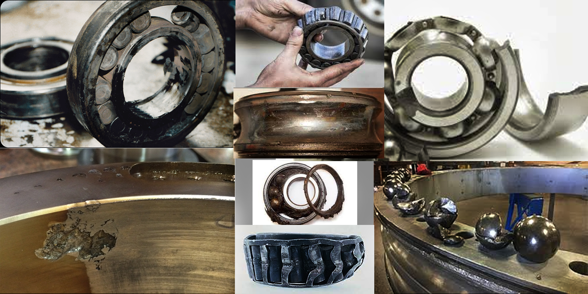
Bearing failures can be a major headache for any facility, causing increased downtime, high-maintenance costs, missed deliveries, loss of revenue...
What Is a Flanged Sleeve Bearing? In most shaft-and-housing assemblies, retaining a plain bushing axially requires either a shoulder machined into...