

 Robert
Wind Turbine Slewing Bearings: Pitch, Yaw & Selection Guide
Wind turbines depend on precise, reliable rotation at every level — from individual blade angle adjustments to full nacelle orientation. The...
Wind energy has become one of the world's fastest-growing renewable energy sources, with global installed capacity surpassing 1,000 GW. But behind every megawatt of clean energy spinning into the grid lies a complex mechanical system where a single component failure can cost hundreds of thousands of dollars in downtime, repairs, and lost revenue.
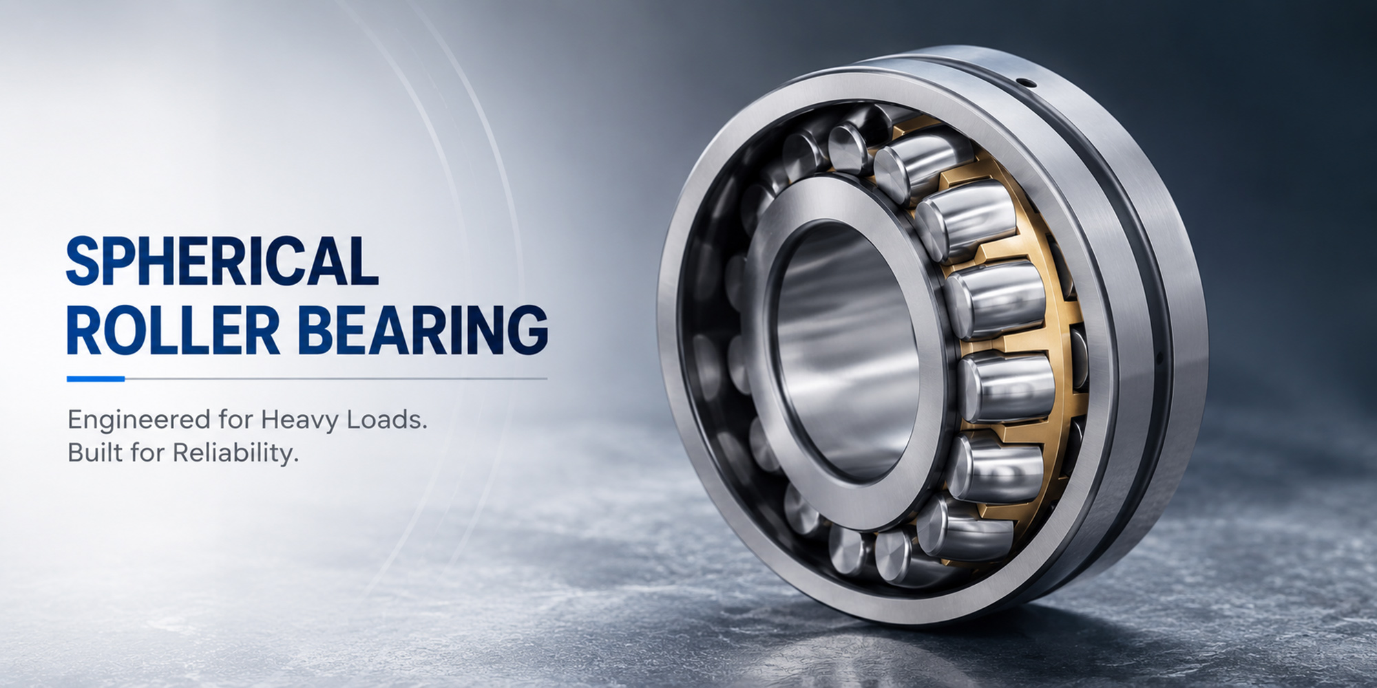
Spherical roller bearings (SRBs) are among the most critical components in a wind turbine's drivetrain. Positioned inside the gearbox — the mechanical heart of the turbine — these bearings must endure decades of operation under extreme and constantly changing loads, all while spinning at high speed in remote, difficult-to-access locations.

This article provides a comprehensive engineering analysis of the challenges spherical roller bearings face in wind turbine gearboxes — and the solutions that modern engineers and bearing manufacturers have developed to overcome them.
Before diving into wind turbine applications, it's worth understanding what makes a spherical roller bearing unique. Unlike deep groove ball bearings or cylindrical roller bearings, SRBs feature a specific geometry that allows them to accommodate angular misalignment while carrying both radial and axial loads simultaneously.

|
Component |
Material |
Function |
Critical Spec |
|
Outer Ring |
Through-hardened 100Cr6 |
Fixed raceway; transmits load to housing |
Spherical inner surface for self-alignment |
|
Inner Ring |
Through-hardened or case-hardened steel |
Rotates with shaft; distributes load to rollers |
Double-row raceway at ~25° contact angle |
|
Barrel Rollers |
High-carbon chrome steel or Si3N4 |
Transmit radial + axial loads |
Barrel shape allows misalignment compensation |
|
Cage / Retainer |
Stamped steel, brass, or polyamide |
Separates rollers; maintains even spacing |
Must withstand centrifugal forces at high RPM |
|
Seals / Shields |
Nitrile rubber, PTFE, or steel |
Retain lubricant; exclude contaminants |
Critical in contaminated environments |
💡 Key Advantage: The spherical outer raceway allows the bearing to tolerate shaft deflections and housing misalignment of up to ±2.5° — a critical feature in wind turbine gearboxes where structural flexing under variable loads is unavoidable.
A modern multi-megawatt wind turbine gearbox is a marvel of mechanical engineering. It takes slow rotor shaft rotation (typically 5–15 RPM) and amplifies it to 1,500–1,800 RPM for the generator — a gear ratio of 100:1 or more. Spherical roller bearings are deployed at multiple stages throughout this system.

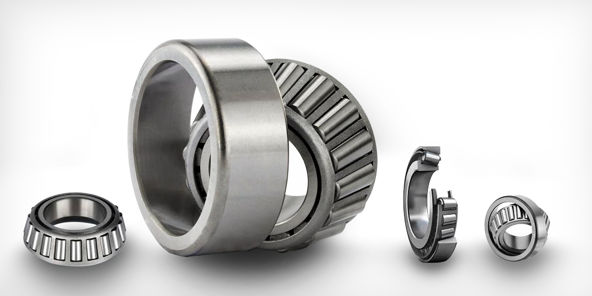
In a typical 3-stage gearbox, SRBs are used predominantly in the first and second planetary stages, where radial and combined loads are highest. As speeds increase toward the generator, cylindrical roller bearings or tapered roller bearings are sometimes substituted — but SRBs remain dominant where misalignment tolerance is essential.
Wind turbines operate in some of the harshest mechanical environments imaginable. Unlike industrial machinery running at consistent speeds and loads, wind turbines constantly change their operating conditions, creating a uniquely demanding set of challenges for their bearing systems.
The most notorious and poorly understood failure mode. WECs form subsurface cracks invisible to standard inspection, causing sudden catastrophic failure — often in 5–10% of expected bearing life.
During standstill or low-load operation, micro-oscillations cause fretting damage and indentations at roller contact points, accelerating pitting and wear initiation.
High operating temperatures, water ingress, and oil film collapse under dynamic loads cause lubricant breakdown, directly leading to metal-to-metal contact and surface fatigue.
Stray electrical currents from the generator can pass through bearings, creating micro-craters (electrical discharge machining / EDM pitting) on rolling surfaces.
Wind gusts, grid events, and emergency stops create load spikes 3–5× higher than calculated design loads, overwhelming the bearing's dynamic load rating.
Offshore turbines and those in humid environments face accelerated corrosion, hydrogen embrittlement, and abrasive particle contamination in the lubricant film.
|
Challenge |
Failure Mode |
Frequency |
Severity |
Detectability |
|
White Etching Cracks |
Subsurface fatigue spalling |
Very Common |
CRITICAL |
Very Low |
|
False Brinelling |
Surface indentation, pitting |
Common |
High |
Moderate |
|
Lube Degradation |
Surface fatigue, scuffing |
Common |
High |
Good |
|
Electrical Pitting |
EDM craters, fluting |
Moderate |
High |
Moderate |
|
Dynamic Overload |
Subsurface cracks, spalling |
Occasional |
CRITICAL |
Moderate |
|
Contamination |
Abrasive wear, corrosion |
Common (offshore) |
High |
Good |
The bearing industry has responded to the wind energy sector's demanding requirements with a range of innovations, spanning materials science, surface engineering, lubrication chemistry, and digital monitoring technologies.
Traditional through-hardened 100Cr6 steel remains the baseline, but leading manufacturers now offer carbonitrided steel grades that significantly improve resistance to WECs. The case-hardened layer absorbs subsurface stress differently, inhibiting crack nucleation.
Creates a nitrogen-enriched surface layer that retards the phase transformation responsible for WEC formation. Increases bearing life by 2–4× in WEC-prone applications.
Improves corrosion resistance and provides a sacrificial layer during run-in, reducing early-life surface distress and micropitting under mixed lubrication conditions.
Extremely hard, low-friction coatings applied to roller surfaces. Proven to reduce smearing and adhesive wear under slip conditions during rapid load changes.
Silicon nitride (Si₃N₄) rollers in steel rings offer electrical insulation, 40% lower density (reducing centrifugal loading), and superior hardness for contaminated environments.
The lubricant is the bearing's first line of defense. Advances in grease and oil formulation have dramatically extended service intervals and improved performance under the cyclic loading characteristic of wind turbines.
|
Lubricant Technology |
Target Challenge |
Performance Benefit |
Application Stage |
|
PAO Synthetic Base Oil + EP Additives |
Film breakdown, thermal degradation |
Stable viscosity across -30°C to +120°C |
All stages |
|
Anti-WEC Additive Packages |
White Etching Cracks |
Reduces WEC incidence by 60–80% |
High-load stages 1 & 2 |
|
Ionic Liquid Additives |
Wear and friction under slip |
Tribofilm formation at low concentrations |
Emerging / premium |
|
Micropump Circulation Systems |
Lubricant starvation, contamination |
Continuous fresh oil supply; particle filtration |
Offshore/large turbines |
To prevent EDM pitting caused by stray currents, engineers have developed multiple strategies. Ceramic (Si₃N₄) hybrid bearings provide inherent electrical insulation. Alternatively, aluminum oxide or zirconia-coated outer rings (insulated bearings) break the electrical circuit while maintaining conventional steel contact geometry.
🔌 Best Practice: Always ground the generator shaft through a dedicated shaft grounding ring. Combine with at least one insulated bearing per shaft position to eliminate both axial current paths and loop currents in the drivetrain.
Perhaps the most transformative development in wind turbine bearing management is the shift from time-based maintenance to condition-based and predictive maintenance (PdM). Advanced sensor arrays can now detect bearing faults weeks or months before catastrophic failure.
|
Monitoring Technology |
Detection Capability |
Lead Time |
Implementation Cost |
|
Vibration Analysis (MEMS) |
Spalling, looseness, imbalance |
4–12 weeks |
Low–Medium |
|
Acoustic Emission (AE) Sensors |
Early micro-crack formation |
8–20 weeks |
Medium–High |
|
Oil Particle Counters |
Wear debris, contamination |
6–16 weeks |
Low–Medium |
|
Thermal Imaging (IR) |
Friction overheating, lube failure |
1–4 weeks |
Low |
|
Digital Twin Models |
Remaining useful life (RUL) prediction |
Months to years |
High |
While spherical roller bearings dominate wind turbine gearbox applications, engineers must sometimes choose between competing technologies. Here is how the main contenders compare:
|
Bearing Type |
Radial Load |
Axial Load |
Misalignment |
Speed |
Best Position |
|
Spherical Roller Bearing (SRB) |
Very High |
High (bidir.) |
±2.5° (excellent) |
Moderate |
Stages 1 & 2, main shaft |
|
Cylindrical Roller Bearing (CRB) |
Very High |
None / Low |
Very Low (<0.04°) |
High |
Stage 3, high-speed shaft |
|
Tapered Roller Bearing (TRB) |
High |
Very High |
Low (<0.05°) |
Moderate |
Output shaft, axial-loaded pos. |
|
Deep Groove Ball Bearing |
Moderate |
Moderate |
Low (<0.1°) |
Very High |
Generator bearings |
|
CARB Toroidal Bearing |
Very High |
None (float) |
±0.5° + axial float |
Moderate |
Floating pos. (paired with SRB) |
⚙️ Engineering Insight: The most robust gearbox designs combine a fixed-position SRB (handling both radial and axial loads) with a floating CARB or CRB bearing. This accommodates thermal shaft expansion while ensuring precise axial location at the fixed end.
Even the best bearing will fail prematurely without proper maintenance. Wind turbines present unique maintenance challenges: they are often located in remote or offshore locations, and the cost of access can rival the cost of the parts themselves. This makes preventive maintenance ROI exceptionally high.
|
Maintenance Task |
Interval |
Method |
Impact on Bearing Life |
|
Oil Analysis (viscosity, particles, water) |
Every 3–6 months |
Inline sensor or lab sample |
High (+30% life extension) |
|
Vibration Signature Analysis |
Continuous / monthly |
Online CMS or portable analyser |
Very High (avoids unplanned failures) |
|
Oil Change / Top-Up |
Annually or per oil analysis |
Drain-and-fill with approved grade |
High |
|
Filter Replacement |
Every 6 months |
Differential pressure indicator |
Moderate |
|
Alignment Check |
At install & after major events |
Laser alignment tool |
High (prevents premature wear) |
|
Shaft Grounding Inspection |
Annually |
Visual + resistance measurement |
Moderate (prevents EDM damage) |
As turbine ratings climb above 15 MW for offshore platforms, and as the industry pushes to extend service life to 25–30 years, bearing technology must continue to evolve. Several key trends are shaping the future of spherical roller bearings in wind applications.
Machine learning models trained on fleet-wide vibration, temperature, and oil data can predict individual bearing failures with greater accuracy than traditional threshold alarms, potentially doubling maintenance planning windows.
Research into bainitic steel and powder-metallurgy steel grades promises dramatically improved resistance to WECs and rolling contact fatigue, targeting bearing lives well beyond the 20-year design standard.
Bearings with integrated MEMS sensors measuring load, temperature, and rotation speed directly at the contact zone eliminate sensor-to-bearing signal lag, enabling millisecond-scale anomaly detection.
Floating offshore wind platforms introduce six-degrees-of-freedom motion loads that onshore bearings were not designed for. New SRB geometries with broader roller profiles and enhanced seal systems are under development.
Modern SRBs in wind turbines are designed for a minimum L10 life of 175,000 hours (approximately 20 years) at rated load. However, actual service life varies significantly based on operating conditions, maintenance quality, and the presence of failure-accelerating factors like WECs or contamination. With best practices, 25+ year lives are achievable.
White Etching Crack (WEC)-related premature spalling is consistently cited as the single most prevalent and economically damaging failure mode, accounting for a large share of unplanned gearbox replacements. It is often triggered by a combination of hydrogen embrittlement, lubricant additive chemistry, and dynamic loading conditions.
Yes. Double-row SRBs are capable of handling bidirectional axial loads in addition to high radial loads. The typical design contact angle (around 25°) provides meaningful axial load capacity. For positions with extreme axial loading, tapered roller bearings or paired angular contact bearings may be preferred, but SRBs handle most gearbox positions effectively.
Most wind turbine OEMs specify gear oils with ISO VG 220 to VG 320 viscosity grades for the main gearbox. The specific recommendation depends on operating temperature range, turbine model, and the gearbox manufacturer's specifications. Always refer to the turbine OEM's maintenance manual and use lubricants that carry OEM approval certifications.
The most effective strategy combines shaft grounding rings (which provide a low-resistance discharge path bypassing the bearings), insulated bearing designs (ceramic-coated outer rings or full ceramic hybrid bearings), and regular resistance testing. For new turbine designs, insulated bearings on at least one position per shaft are now considered standard practice.
Yes. Large double-row SRBs or specially designed main shaft bearings are commonly used on the rotor main shaft to support the massive cantilever load of the rotor hub and blades. These bearings are particularly critical because they must operate at very low speeds under extremely high combined radial and moment loads, and are virtually impossible to access without a crane.
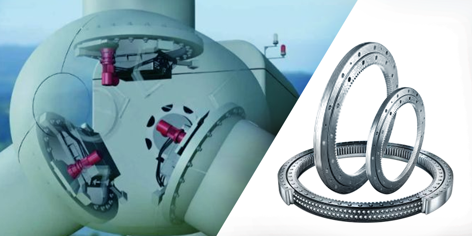
Wind turbines depend on precise, reliable rotation at every level — from individual blade angle adjustments to full nacelle orientation. The...
Not long ago, LYC developed a set of 16 MW platformwind power spindle bearings. The bearings have beenthe largest poweredwind power spindle...
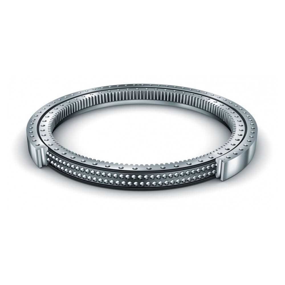
As a major bearing manufacturer in China bearing industry, Lily Bearing is well-known for developing all sorts of sophisticated slewing bearings, one...