

 Robert
Needle Bearings in Robotics: Achieving Torque Density and Precision
In the world of robotics, the glory usually goes to the complex code and the vision systems. Flashy end-effectors also often take the spotlight. At...
A motor bearing rated for 20,000 hours failed in under 800. The root cause wasn't load, speed, or lubrication. It was the wrong radial play group — off by just one step.
That kind of failure is more common than most engineers expect. And it's almost always preventable.
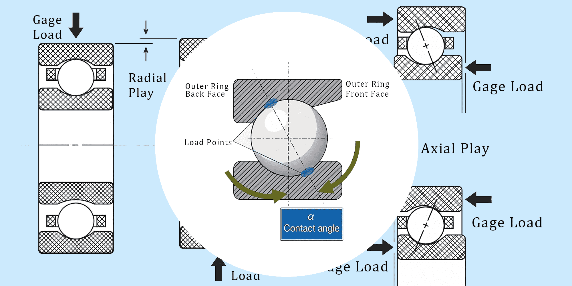
Radial play, axial play, and contact angle are the three internal geometry parameters that determine how a ball bearing distributes load, handles thrust, and survives real operating conditions.
Change one and you change all three. Get the combination wrong and you get noise, heat, vibration, and early failure.
Get it right and the bearing runs quietly and outlasts its rated life — with real numbers, not vague guidelines.
Radial play (also called internal clearance) is the total side-to-side movement of the outer ring relative to the inner ring, measured perpendicular to the bearing axis, in an unmounted and unloaded state.
In plain terms: it's the intentional looseness built into every bearing at the factory.

Typical values run from 0.0002 inches (0.005 mm) on the tight end to 0.002 inches (~0.051 mm) on the loose end for standard deep groove ball bearings.
That's a range smaller than a human hair on one end, and about the thickness of a sheet of paper on the other.
Small differences matter enormously.
One thing that surprises many engineers: radial play has nothing to do with bearing precision grade.
A P4 (ABEC 7) precision bearing can have loose radial play.
A standard P0 (ABEC 1) bearing can have tight radial play.
They're specified and controlled completely independently.
Without some internal looseness, a bearing would be nearly impossible to install.
When a bearing is press-fitted onto a shaft, the inner ring expands slightly.
When pressed into a housing, the outer ring compresses slightly.
Both reduce effective internal clearance after mounting.
Starting at zero clearance means ending up with negative clearance — a bearing that preloads itself to destruction during installation.
There's also thermal expansion.
During operation, the inner ring typically runs hotter than the outer ring. Without built-in clearance to absorb differential expansion, the bearing locks up.
Most manufacturers follow this classification system:
MC3 is the default for most radial bearing applications.
It's what you get when you order a standard bearing without specifying a clearance group.
It's not always the right choice — but it's the right starting point for most general-purpose designs.
Axial play (also called end play or axial clearance) is the maximum in-and-out movement along the shaft axis between the inner and outer rings.
If radial play is side-to-side, axial play is fore-and-aft.

Same looseness, different direction.
Published ranges vary by bearing size and series.
Industry engineering reference cites .001 to .020 inches as a general range for ball bearings.
What's consistent across all sizes: axial play is always several times larger than radial play for the same bearing.
That's not a manufacturing issue — it's a geometric consequence of how balls sit in curved raceways.
Radial and axial play aren't independent. They're two consequences of the same internal looseness:
PE = √(4Bd × PD − PD²)
Where:
PE = axial play,
PD = radial play,
B = total curvature (fi + fo − 1),
d = ball diameter.
This means specifying radial play implicitly sets axial play.
Most bearing part numbers only list the radial play group — axial play is either calculated or measured during assembly.
For most radial-load applications, radial play is the number you specify. But axial play becomes the critical parameter when:
Shaft end float must be controlled tightly — linear positioning stages, gear assemblies where mesh clearance matters, cam mechanisms where timing is critical
Seals depend on axial position — even 0.005 inches of unexpected axial float can compromise a face seal
Duplex bearing pairs are used and the installed preload must be verified
When zero axial float is required, the solution is preload — not specifying a tighter radial play group. Using MC2 to control end play is a common mistake. It doesn't solve the problem and creates negative clearance risk after mounting.
The contact angle is the angle between a plane perpendicular to the bearing axis and the line connecting the ball's contact points on the inner and outer raceways.

When there's no load and no preload, that line passes through the deepest part of both raceways.
Apply axial load — or increase radial play — and the balls shift.
The contact angle increases.
Standard deep groove ball bearings carry initial contact angles roughly between 5° and 30°, depending on ball size and radial play group.
The initial contact angle (a₀) — established when just enough axial load is applied to remove internal looseness — can be calculated two ways:
a₀ = cos⁻¹ [(2Bd − PD) / 2Bd]
a₀ = sin⁻¹ [PE / 2Bd]
Both give the same result.
Use whichever variable you've already calculated.
Once running under combined load, the operating contact angle diverges from the initial value.
Every additional increment of axial load pushes it higher.
Smaller balls produce steeper contact angles for identical radial play.
From published contact angle data (fi = fo = 0.56, MC3 mean radial play of 0.0003 inches):
Same clearance, same curvature — but the smallest ball sits at more than twice the contact angle of the largest.
This directly affects load capacity and must feed into your load rating calculations.
Treat them as one number with three faces — change any one and the other two move with it:
Higher radial play → higher contact angle → higher axial play
Lower radial play → lower contact angle → lower axial play
Axial preload → zero radial play → fixed, defined contact angle
Radial play is the input. Contact angle and axial play follow from it.

Track curvature — the track radius expressed as a percentage of ball diameter — typically runs 52% to 58% and feeds directly into every contact angle calculation via total curvature B = (fi + fo − 1).
52–54%: Tighter conformity, lower contact stress, better for heavy loads
55–58%: More clearance between ball and raceway, lower friction, better for low-torque or high-speed use
Below 52%: Excessive rolling friction — avoid
Above 58%: Ball-to-raceway contact stress becomes dangerously high — avoid
A bearing with fi = fo = 0.56 gives B = 0.12.
Change the curvature and the contact angle changes — even with identical radial play and ball diameter.
Always confirm curvature when comparing bearings from different manufacturers.
When a bearing is press-fitted onto a shaft or into a housing, the rings deform slightly and internal clearance drops.
How much depends on shaft diameter, housing bore, material, and interference class — there's no single number that applies universally.
The practical rule: always start one clearance group looser than your target operating clearance.
If you need MC3 in operation, specify MC4 unmounted.
Then verify against your bearing supplier's interference fit tables for your specific dimensions.
Skipping this step is one of the most common causes of premature bearing failure in interference-fitted applications.
Pure radial loads: use MC2 or MC3.
Lower radial play distributes load across more balls simultaneously, reducing peak contact stress at each ball-raceway interface.
Combined or predominantly axial loads: use MC4 or MC5.
A 15° increase in contact angle reduces ball-to-raceway contact stress by over 70% under pure thrust conditions.
In a motor cycling axial loads all day, that difference translates directly into bearing life — sometimes the difference between 2,000 hours and 10,000 hours.
High contact angles reduce stress under axial load, but they create problems at speed.
As RPM increases, gyratory forces act on the balls — and those forces scale with contact angle.
At high speeds, a large contact angle causes sliding between balls and raceways, which breaks down the lubricant film, generates heat, and accelerates failure.
For a spindle running at 30,000 RPM, even MC3 may be too loose.
Many high-speed applications use preloaded pairs to lock in a specific, optimized contact angle.
When the inner ring runs hotter than the outer ring — common in electric motors, pumps, and gearboxes — the shaft expands and squeezes the bearing from the inside, reducing effective internal clearance during operation.
Design rule: when inner ring temperature is expected to run 20°C or more above the outer ring, step up one clearance group from what the load analysis recommends.
Some applications can't tolerate any internal play at all — machine tool spindles, instrument bearings, servo actuators, optical systems.
The solution is axial preload: applying a controlled axial force across a bearing pair to eliminate looseness entirely and establish a defined contact angle.
Common preload methods:
Wave or spring washers on the stationary ring (which should have a sliding fit to allow axial movement)
Precision shim stacks where tight control of preload magnitude is needed
Take-up nuts on shaft-mounted configurations
Adhesive-cured pairs, where weighted fixtures hold position during cure
The contact angle that results from preloading depends on the starting radial play — which in turn determines how the preloaded pair splits axial versus radial load capacity.
More preload = more stiffness — up to a point. Excessive preload raises frictional torque sharply and causes rapid failure at high speeds. Target the minimum preload that achieves required stiffness, with margin for worst-case thermal conditions.
Because radial play allows the inner ring to tilt slightly relative to the outer ring, every ball bearing can accommodate a small degree of shaft-to-housing misalignment.
This is called the free angle of misalignment.
In real-world assemblies, shaft and housing centerlines are never perfectly aligned.
A small amount of built-in misalignment tolerance — which comes directly from radial play and track curvature — absorbs those variations without concentrated stress.
A bearing with MC5 clearance and 56% curvature tolerates noticeably more misalignment than one with MC2.
The hard rule: actual misalignment must never exceed the bearing's free angle of misalignment.
Beyond that point, load distribution becomes severely uneven and fatigue life collapses.
Radial play is measured on an unmounted, unloaded bearing using a precision fixture and dial indicator.
A standard gage load seats all components; the outer ring is displaced radially and total movement is recorded.
For miniature bearings, elastic deformation under gage load can inflate the reading — manufacturers publish compensation factors for this.
Axial play is rarely measured at purchase for standard bearings — it's calculated from the radial play spec using the formula above.
For precision assemblies where end float must be verified, direct axial measurement during assembly is standard practice.
Radial play is the primary specification — axial play and contact angle follow from it automatically.
The right radial play depends on fit, load type, speed, and thermal environment.
Most bearing failures that get blamed on lubrication or overload trace back to a clearance group that was wrong for the application — often because the engineer used MC3 by default and never questioned it.
Use the tables and formulas in this article to make the decision deliberately.
The bearing that's been quietly running for 15 years in a piece of equipment didn't get there by accident — someone specified the right internal geometry from the start.

In the world of robotics, the glory usually goes to the complex code and the vision systems. Flashy end-effectors also often take the spotlight. At...
In the intricate realm of aerospace, ball bearings serve a pivotal role, ensuring precision, efficiency, and durability in various mechanical systems.
You’re designing a linear axis and the question comes down to drive selection: ball screw, belt, or gear rack? For most engineers, the tipping point...