

 Richard
L10 Fatigue Life and Internal Clearance: What Every Spindle Engineer Must Know
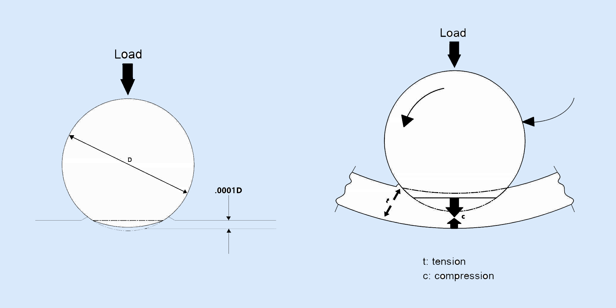
Key Takeaways → The ISO 281 L10 formula assumes zero internal clearance — an assumption no real spindle meets → Three factors consume initial...

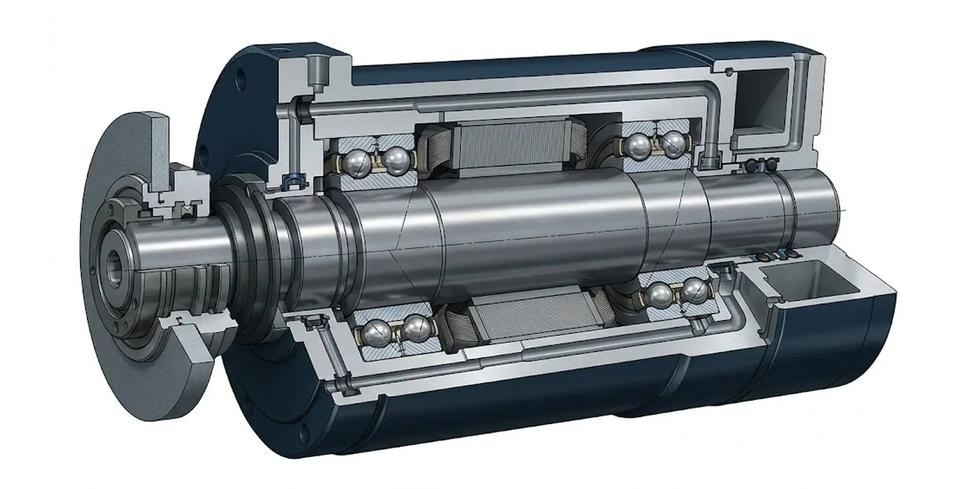
Spherical roller bearings (SRBs) are double-row rolling-element bearings equipped with barrel-shaped (asymmetric) rollers and a common sphered outer raceway. Their hallmark feature is self-alignment: the curved outer ring allows the shaft to deviate up to ±3° from its nominal centerline without inducing catastrophic edge loading on the rollers.
This makes SRBs the preferred choice for heavy industrial machinery where shaft deflection, housing misalignment, and thermal expansion are facts of life — not exceptions. Think: paper mill rolls, mining conveyor drives, large gearboxes, wind turbine main shafts, and rolling mill equipment.
|
💡 Key Engineering Insight Unlike cylindrical roller bearings, spherical roller bearings can handle both radial and axial loads simultaneously — a critical advantage in real-world machinery where forces rarely act in a single direction. |
Bearing selection is not a guessing game. Undersized bearings fail early, causing unplanned downtime, production losses, and safety hazards. Oversized bearings waste money, add mass, and may not even fit. Accurate bearing life calculation is the bridge between those two costly extremes.
For spherical roller bearings — which are often deployed in the heaviest, most demanding applications in industry — the stakes are especially high. A single failed main bearing on a cement kiln or a wind turbine can cost hundreds of thousands of dollars in repairs and lost production.
|
⚠️ Engineering Rule Always calculate bearing life before finalizing a design. Retrofitting a larger bearing after a field failure typically costs 10–50× more than getting the selection right the first time. |
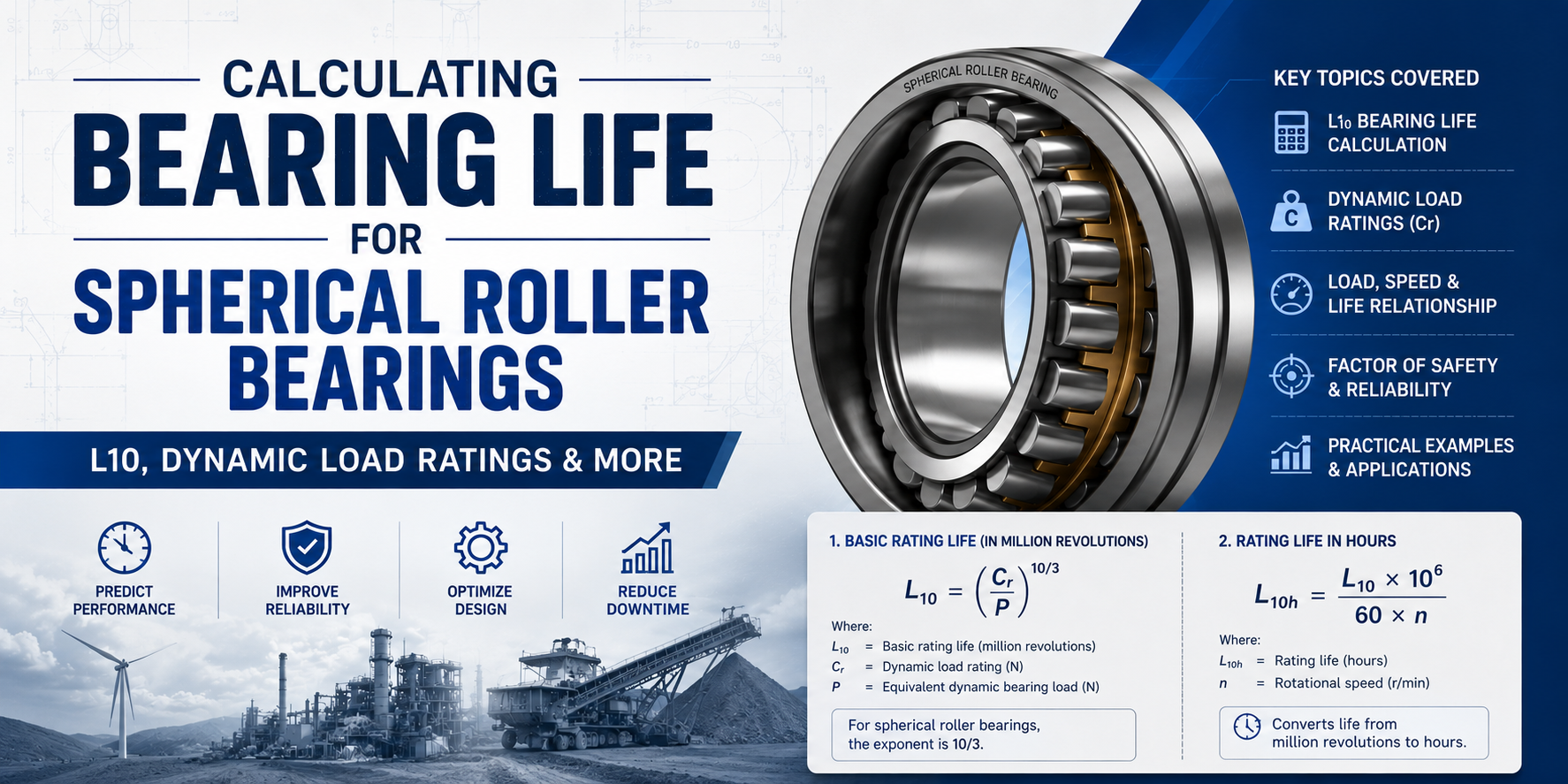
The L10 life is the cornerstone of modern bearing life calculation. It is defined as the number of revolutions at which 90% of a group of identical bearings, operating under identical conditions, will still be running without fatigue failure. Conversely, 10% of bearings will have failed before this point — hence the term "basic rating life at 90% reliability."
L10 is expressed in millions of revolutions (10⁶ rev), or more practically in operating hours (L10h):
|
CONVERSION: MILLIONS OF REVOLUTIONS TO HOURS L10h = (L10 × 10⁶) / (60 × n) L10h = Life in hours n = Rotational speed [RPM] |
|
Application |
L10h Target |
Reliability |
Notes |
|
Household appliances |
1,000–3,000 h |
Standard |
Short product life |
|
Agricultural machinery |
3,000–5,000 h |
Standard |
Seasonal use |
|
Industrial gearboxes |
10,000–25,000 h |
High |
3-shift continuous |
|
Paper & steel mills |
40,000–60,000 h |
High |
Critical; hard to replace |
|
Wind turbine main shaft |
100,000+ h |
Very High |
~20-year design life |
|
Mining conveyor drives |
50,000–80,000 h |
High |
Remote locations |
The internationally recognized standard for bearing life calculation is ISO 281. For spherical roller bearings, the exponent n = 10/3 applies (unlike ball bearings which use n = 3), reflecting their line-contact geometry:
|
ISO 281 — BASIC RATING LIFE (ROLLER BEARINGS) L10 = (Cr / P)^(10/3) L10 = Basic rating life [10⁶ rev] Cr = Dynamic load rating [kN] P = Equivalent dynamic load [kN] |
Before applying the L10 formula, radial and axial forces must be combined into a single equivalent dynamic load P:
|
EQUIVALENT DYNAMIC BEARING LOAD P = X · Fr + Y · Fa Fr = Radial force [kN] Fa = Axial force [kN] X = Radial factor (from catalog) Y = Axial factor (from catalog) |
|
�� Important The X and Y factors are not constant — they depend on the ratio Fa/Fr and the contact angle of the specific bearing series. Always obtain them from the manufacturer's catalog for the exact model being used. |
The dynamic load rating Cr is a standardized value calculated per ISO 281. It represents the constant radial load a bearing can theoretically endure for exactly one million revolutions at 90% reliability. It is the single most important number in a bearing catalog.
|
Designation |
Bore (mm) |
Cr (kN) |
C0r (kN) |
Mass (kg) |
Typical Application |
|
22208 E |
40 |
71 |
85 |
0.42 |
Small gearboxes |
|
22215 E |
75 |
230 |
270 |
2.05 |
Industrial fans |
|
22228 E |
140 |
630 |
850 |
14.0 |
Conveyor drives |
|
23238 CC/W33 |
190 |
1,320 |
1,900 |
48.0 |
Steel mill rolls |
|
23260 CC/W33 |
300 |
3,350 |
5,000 |
250 |
Wind turbine shafts |
|
24192 ECAK30 |
460 |
7,100 |
11,800 |
1,050 |
Mining crushers |
|
⚠️ Warning Always use the Cr value from the specific manufacturer's catalog for the bearing model you are using. Values vary between manufacturers due to internal geometry differences. Do not mix catalog data across brands. |
The basic L10 formula assumes ideal conditions: perfect lubrication, no contamination, normal temperature, and standard steel. Real applications rarely meet all of these. The modified rating life Lnm accounts for real-world operating conditions:
|
MODIFIED RATING LIFE — ISO 281 Lnm = a1 · aISO · L10 a1 = Reliability factor aISO = Life modification factor (lubrication, contamination, fatigue limit) |
|
Reliability (%) |
Failure Prob. (%) |
a1 |
Life vs. L10 |
Use When |
|
90% (L10 Standard) |
10% |
1.00 |
1.0× |
Standard industrial |
|
95% |
5% |
0.62 |
0.62× |
Higher reliability needed |
|
97% |
3% |
0.44 |
0.44× |
Critical machinery |
|
98% |
2% |
0.33 |
0.33× |
Safety-critical systems |
|
99% |
1% |
0.21 |
0.21× |
Aerospace, nuclear |
The viscosity ratio κ compares the actual kinematic viscosity of oil at operating temperature (ν) to the required reference viscosity (ν₁):
|
VISCOSITY RATIO κ = ν / ν₁ ν = Actual viscosity at operating temp [mm²/s] ν₁ = Reference viscosity from catalog [mm²/s] |
|
κ Value |
Condition |
Effect on aISO |
Action |
|
κ < 0.4 |
Severely Starved |
aISO drastically reduced |
Increase viscosity or reduce speed immediately |
|
κ = 0.4–1.0 |
Marginal Film |
aISO < 1.0 |
Consider EP additives or higher-viscosity oil |
|
κ = 1.0–4.0 |
Good Lubrication |
aISO ≥ 1.0 |
Optimal zone — maintain conditions |
|
κ > 4.0 |
Full EHD Film |
aISO maximized |
Ideal — watch viscous drag at low temps |
|
📐 Scenario An industrial conveyor drive shaft runs at n = 480 RPM. Radial force Fr = 85 kN; axial force Fa = 18 kN. Selected bearing: 22228 E (Cr = 630 kN; X = 1, Y = 2.8 for this Fa/Fr ratio). Target life: 40,000 hours. Does this bearing meet the requirement? |
|
Step |
Calculation |
Result |
|
1. Equivalent load P |
P = 1 × 85 + 2.8 × 18 |
P = 135.4 kN |
|
2. Load ratio Cr/P |
630 / 135.4 |
= 4.653 |
|
3. L10 (millions of rev) |
L10 = (4.653)^(10/3) |
≈ 148 million rev |
|
4. Convert to hours |
L10h = (148 × 10⁶) / (60 × 480) |
≈ 5,139 hours |
|
5. Compare to target |
5,139 h vs. 40,000 h target |
❌ Does NOT meet target |
|
6. Recommendation |
Upgrade to 23238 CC/W33 (Cr = 1,320 kN) |
✔ Recalculate with new bearing |
|
📊 Lesson A bearing that looks large enough by bore size can fall far short of required life when actual loads are applied. Always run the calculation — never rely on intuition alone. |
|
Application |
Speed (RPM) |
Load Type |
L10h Target |
Key Consideration |
Preferred Series |
|
Wind turbine main shaft |
10–20 |
Very high radial + variable axial |
100,000+ |
Fatigue, contamination |
232xx, 241xx |
|
Paper mill rolls |
200–600 |
High radial, shock |
50,000–80,000 |
Water contamination |
222xx CC/W33 |
|
Mining crushers |
100–400 |
Extreme radial + shock |
30,000–50,000 |
Heavy dirt, impact |
240xx, 241xx |
|
Industrial gearboxes |
300–1,500 |
Moderate radial + axial |
20,000–40,000 |
Speed, oil viscosity |
222xx E, 223xx E |
|
Centrifugal pumps |
1,000–3,000 |
Moderate radial |
20,000–30,000 |
Misalignment, deflection |
222xx E |
|
Steel mill roll necks |
50–300 |
Very high radial + shock |
40,000–60,000 |
High load, water cooling |
230xx, 232xx |
Even a correctly selected and calculated bearing can fail early if installed or maintained improperly. Understanding failure modes prevents costly surprises.
|
Failure Mode |
Visual Signs |
Root Cause |
Prevention |
|
Surface fatigue / spalling |
Pitting, flaking on raceways |
Exceeding Cr; incorrect L10 |
Recalculate with actual loads; upsize bearing |
|
Smearing |
Torn, shiny raceway patches |
κ < 0.4; oil starvation |
Increase oil viscosity; pre-lube at startup |
|
False brinelling |
Dents at roller pitch spacing |
Micro-vibration while stationary |
Anti-fretting grease; lock shaft during storage |
|
True brinelling |
Deep indentations in raceway |
Shock load exceeding C0 static |
Verify C0 against peak shock loads |
|
Corrosion |
Red/brown staining, pitting |
Water or acid ingress |
Sealed variants; corrosion-inhibiting grease |
|
Cage fracture |
Broken cage, seized roller |
Overspeeding; impact loads |
Observe speed ratings; correct lubricant spec |
Key Takeaways → The ISO 281 L10 formula assumes zero internal clearance — an assumption no real spindle meets → Three factors consume initial...
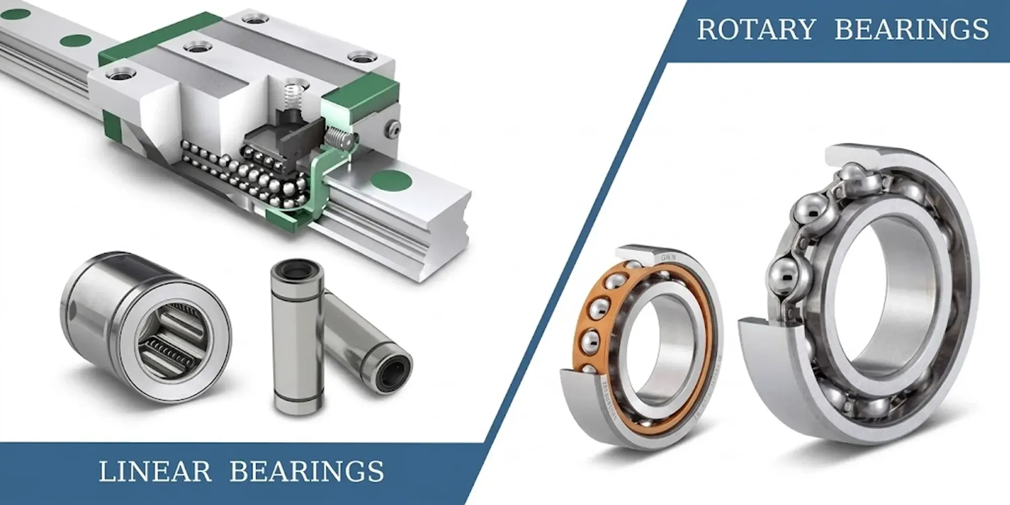
Linear Bearings vs Rotary Bearings — Key Differences Dimension ▶ Linear Bearing ▶ Rotary Bearing Motion type TranslationBack-and-forth...
Bearings play a vital role in machinery by ensuring smooth motion and reducing friction. Understanding load capacities, specifically static load vs...