

 Richard
Linear Bearing Noise & Failure: Causes, Diagnosis & When to Replace
A linear bearing that's failing doesn't always give you much warning. Sometimes it starts with a subtle grinding sound at one end of the stroke. ...
Slewing bearings are built to carry three types of loads simultaneously: axial, radial, and moment loads.
In most real-world installations — cranes, excavators, wind turbines, robotic arms — the dominant design challenge is rarely axial capacity. It's the tilting moment.
Get it wrong, and the bearing races see uneven contact stress, the rolling elements fatigue prematurely, and the surrounding structure starts to deflect. Get it right, and a bearing rated for 20 years can actually deliver it.
This article explains exactly what the tilting moment is, how to calculate it, what amplifies it in practice, and how engineers select and protect bearings against it.
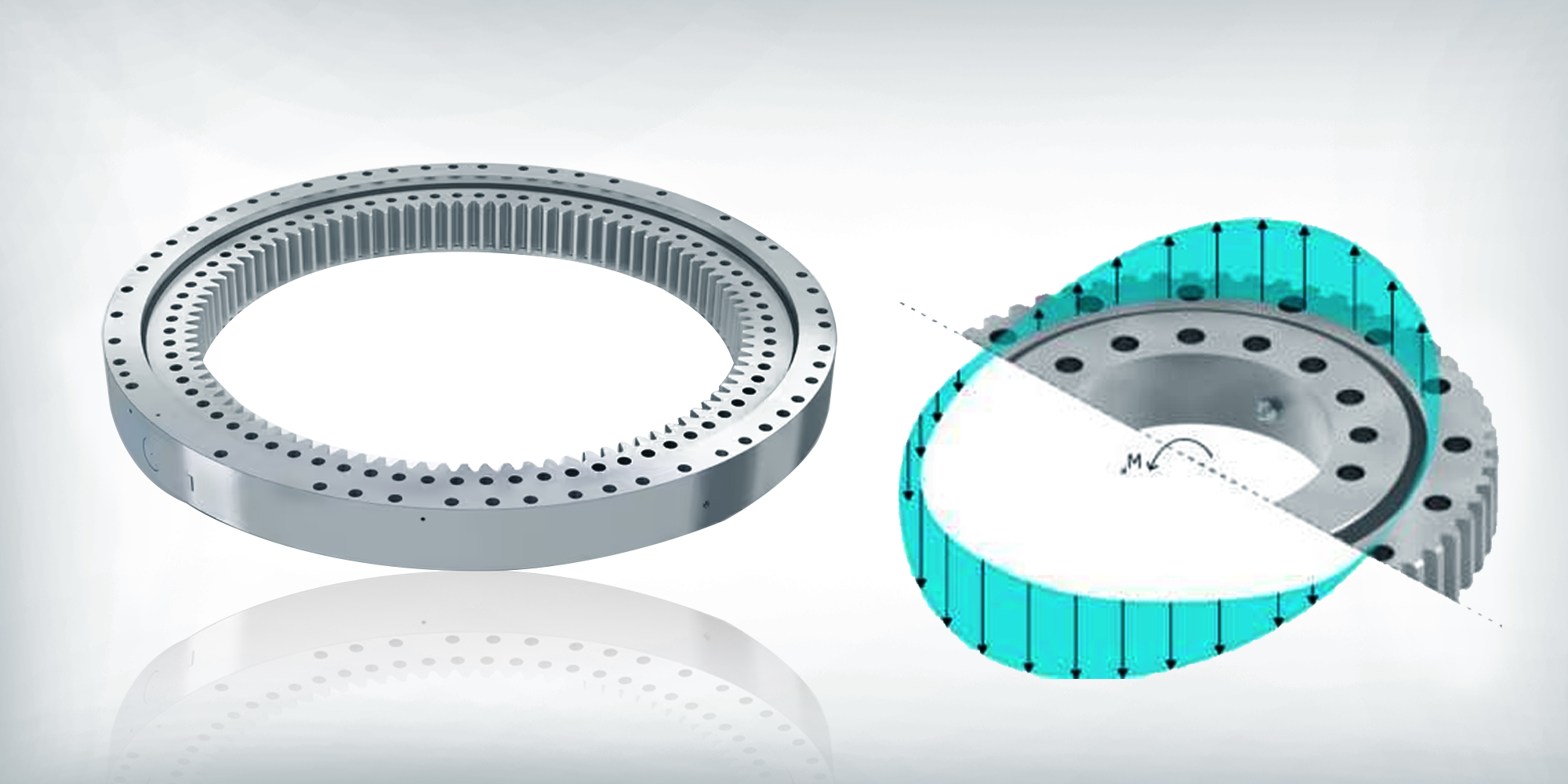
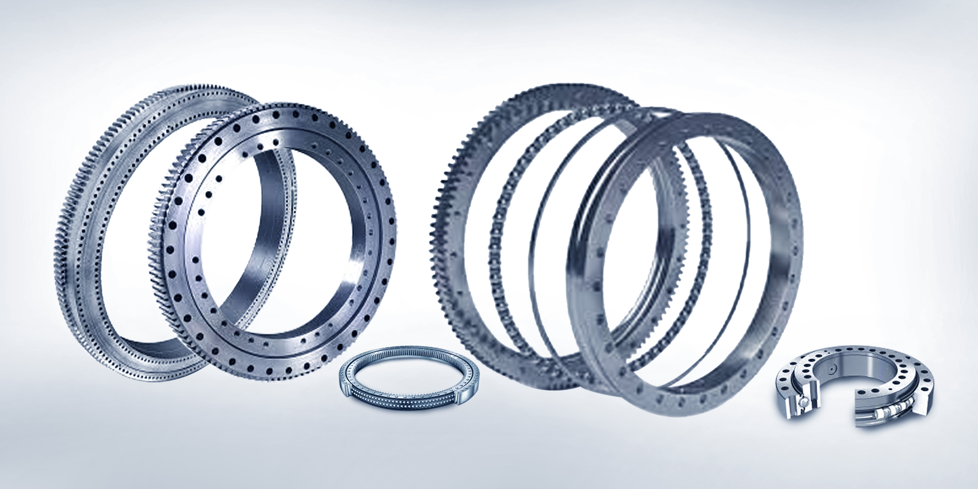
Slewing bearings (also called slewing rings or turntable bearings) are large-diameter rolling-element bearings designed for slow rotation under combined loading.
Unlike standard bearings that handle predominantly one load type, slewing rings must simultaneously manage axial loads (forces parallel to the rotation axis), radial loads (forces perpendicular to the rotation axis), and moment loads — the tilting moment, which is the product of an off-center force and its lever arm.
Diameters commonly range from 200 mm for light industrial robots to over 4,000 mm for offshore crane pedestals.
Rated moment capacities at that scale can exceed 50,000 kN·m.
A tilting moment (also called an overturning moment) arises whenever the resultant load does not pass through the geometric center of the bearing.
That offset creates a lever arm, which tries to tilt the inner ring relative to the outer ring.
Practically: a crane lifts 10 t at a 5 m outreach.
Even with zero radial force, the load's weight acts 5 m from the bearing centerline, generating a tilting moment of 490 kN·m.
That moment is not an axial load — it produces a force couple inside the bearing: compression on one side of the raceway, tension relief (or tension, in some designs) on the opposite side.
This is fundamentally different from a purely axial load, where all rolling elements share the load roughly equally.
Under a tilting moment, load distribution across the rolling elements becomes highly non-uniform, and the most-loaded element can carry 3–5× the average load depending on bearing geometry and stiffness.

| Load Type | Direction | Effect on Raceway |
|---|---|---|
| Axial | Along rotation axis | Relatively even load distribution |
| Radial | Perpendicular to rotation axis | Loads half the raceway, unloads the other half |
| Tilting moment | Rotational — tilts inner ring vs. outer ring | Severe stress concentration; peak element load 3–5× average |
Tilting moments in slewing bearings are rarely caused by a single factor. In practice, multiple sources act simultaneously — and their combined effect is what engineering calculations must capture.
5 Primary Sources of Tilting Moment
① Off-Center Loading
Any load applied at a horizontal distance from the bearing center creates a tilting moment. The longer the boom, the larger the lever arm — regardless of payload weight. This is the dominant source in cranes and excavators.
② Structural Flexibility
A boom or tower that deflects under load shifts the effective force application point. In large lattice-boom cranes, dynamic deflection adds 5–15% to the calculated static moment.
③ Dynamic & Inertial Effects
Slewing at 1 rpm with a 10 t load at 20 m radius adds ~4.4 kN of centripetal radial force. Small in isolation, but it shifts the internal load zone when combined with the base tilting moment.
④ Wind & Environmental Loads
For a 3 MW turbine, rotor thrust at rated wind speed is typically 350–450 kN. Acting at hub height (~80–100 m above the yaw bearing), this generates 28,000–45,000 kN·m on the yaw ring — often the dominant load case.
⑤ Mounting Misalignment
Flatness errors as small as 0.1 mm/m introduce parasitic moment loads outside the original design calculation. ISO 76 recommends specifying supporting structure rigidity and flatness tolerance alongside bearing selection.

The tilting moment is calculated as:
Mt = F × d
Mt = tilting moment (N·m or kN·m) | F = force perpendicular to the rotation axis (N or kN) | d = distance from bearing center to force application point (m)
When multiple loads act simultaneously, tilting moments from each source are summed vectorially.
Most bearing catalogs use an equivalent dynamic load model that combines Fa, Fr, and Mt into a single equivalent bearing load for life calculation per ISO 281.
Given Parameters
Rated lift capacity: 50,000 kg (490.5 kN)
Maximum outreach: 18 m from bearing centerline
Boom weight (at 9 m from center): 120 kN
Wind load on load + boom (at 12 m height): 15 kN
Step 1 — Payload tilting moment
M1 = 490.5 kN × 18 m = 8,829 kN·m
Step 2 — Boom weight tilting moment
M2 = 120 kN × 9 m = 1,080 kN·m
Step 3 — Wind load tilting moment
M3 = 15 kN × 12 m = 180 kN·m
Step 4 — Total (worst-case, all additive)
Mt,total = 8,829 + 1,080 + 180 = 10,089 kN·m
Step 5 — Apply safety factor (1.25 per FEM 1.001)
Mdesign = 10,089 × 1.25 = 12,611 kN·m
Dynamic load factors: Hoisting, slewing, and traveling simultaneously can increase the effective load by 10–30% above static values. FEM and ASME standards provide load combination factors for these scenarios.
Structural compliance: Finite element analysis of the supporting structure is recommended for moment-critical applications, as ring deflection changes the contact angle and load distribution within the bearing.
Load spectrum: Bearings are rarely at maximum load. ISO 281 life calculations require a weighted load spectrum rather than the peak load alone, which can extend calculated L10 life by 2–4×.
Rolling element bearings follow an inverse cube (ball) or inverse 10/3 power (roller) load-life relationship — the basis of the ISO 281 bearing life model.
Even a moderate increase in peak element load has a disproportionate effect on fatigue life.
As a concrete illustration: if uneven load distribution under a tilting moment causes the peak element load to be 1.5× the average, the local fatigue life of that element drops to approximately (1/1.5)³ ≈ 30% of what even distribution would give.
This is why tilting moment capacity — not axial capacity — is the binding design constraint in most slewing ring applications.
Tilting moments increase rolling contact stress asymmetrically, raising the friction torque needed to rotate the bearing.
In large crane swing drives, an unmanaged tilting moment can increase drive motor current draw by 15–25% compared to the design operating point — measurable in energy costs over the equipment's life.
Sustained operation above the rated tilting moment causes raceway spalling, rolling element fracture, and in severe cases, structural failure of the ring.
In mobile cranes, excess tilting moment is a leading cause of catastrophic tip-over.
Both ISO 76 and EN 13001-3-6 require moment load to be explicitly accounted for in bearing selection — it is not conservative to rely on axial capacity alone.
Not all slewing bearing types handle tilting moments equally.
The choice of internal geometry has a significant effect on moment stiffness and capacity.
In our experience, the most common mistake is using axial load capacity as the sole bearing selection criterion — which consistently leads to premature failure in moment-dominant applications.
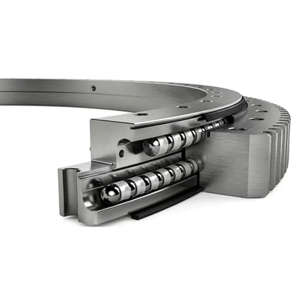
Moment capacity: High | Rigidity: Very High
Alternating rollers at 90° provide line contact across the raceway, distributing load over a larger area than ball contact. Preferred for precision industrial robots, radar antennas, and machine tool rotary tables. Typical moment stiffness: 10³ to 10⁵ N·m/mrad depending on size.
Four-Point Contact Ball Bearings
Moment capacity: Medium–High | Rigidity: Medium
Gothic arch raceway geometry creates four contact points per ball, giving good moment capacity relative to size and weight. Widely used in wind turbine pitch drives and light-to-medium crane applications where mass is a constraint.

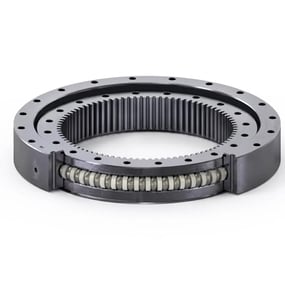
Double-Row Ball Bearings
Moment capacity: Medium | Rigidity: Medium
The separation between the two rows creates an internal moment arm, providing higher moment stiffness than a single-row design of the same outer diameter. Common in excavators and medium-duty cranes.
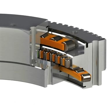
Three-Row Roller Bearings
Moment capacity: Very High | Rigidity: Very High
Dedicated rows for axial load (top and bottom) and radial load (middle) offer the highest load capacity per diameter. Used in the largest cranes and offshore equipment where moment loads exceed 100,000 kN·m.
| Bearing Type | Moment Capacity | Rigidity | Typical Application |
|---|---|---|---|
| Cross roller | High | Very high | Robots, radar, machine tools |
| Four-point contact ball | Medium–High | Medium | Wind turbine pitch, light cranes |
| Double-row ball | Medium | Medium | Excavators, medium cranes |
| Three-row roller | Very high | Very high | Large cranes, offshore |
Minimize lever arms: Positioning the load application point as close to the bearing centerline as practical is the single most effective reduction strategy. Halving the outreach halves Mt.
Increase ring diameter: A larger-diameter bearing distributes the moment couple over a wider base, reducing peak element load for the same external moment. This is why large cranes use rings >2 m in diameter even when a smaller ring might technically pass static checks.
Support structure rigidity: Mounting flanges and supporting structure should meet the flatness tolerances specified by the bearing manufacturer — typically 0.05–0.15 mm/m — to prevent parasitic moments from structural compliance.
Active load monitoring: Load moment indicators (LMIs) measure the actual tilting moment in real time and alert operators before limits are exceeded. This is a legal requirement for most mobile cranes above 1 t capacity in Europe (EN 13000) and the US (ASME B30.5).
Active pitch control (wind turbines): Individually adjusting blade pitch based on wind shear and turbulence reduces asymmetric rotor thrust. Published research on direct-drive turbines shows individual pitch control can reduce peak pitch bearing moment by 20–30%.
Lubrication: Consistent grease replenishment prevents metal-to-metal contact in the raceway. In slow-oscillating bearings like wind turbine pitch rings, false brinelling is a known failure mode; fretting-resistant greases extend raceway life measurably. See our guide on bearing lubrication best practices.
Mounting surface inspection: Check flatness of the mounting flange at each major service interval. Permanent deformation of the supporting structure — particularly in mobile equipment operating on uneven ground — can introduce moments the bearing was not designed to handle.
Vibration and acoustic monitoring: Accelerometers mounted on the bearing housing can detect developing raceway damage at an early stage, typically 2–6 months before a visual inspection would identify the same defect.
In a 100 t lattice boom crawler crane, the slewing bearing may see a tilting moment exceeding 15,000 kN·m at maximum outreach.
The bearing itself weighs 1,500–3,000 kg and requires precise alignment of the upper and lower car bodies to within manufacturer tolerances during assembly.
A common field failure mode is operation on out-of-level ground, which introduces additional tilting moments not accounted for in the crane's original rating.
Most OEM documentation specifies maximum permissible out-of-level gradients — typically 1–3% — for this reason.

A modern 5 MW turbine has three pitch bearings (~2 m diameter each) and one yaw bearing (~3–4 m diameter).
The pitch bearings experience oscillating tilting moments driven by gravity as the blade rotates — a 60 m blade weighing ~15 t generates a gravitational tilting moment of approximately 4,400 kN·m at the 3 o'clock and 9 o'clock positions.
This oscillating load at low amplitude — rather than a single large overload — is what drives fatigue damage.
It is the reason wind turbine bearings are designed using rainflow-counted load spectra rather than a single peak design load.

Six-axis industrial robots use slewing bearings at the base (axis 1) and in some wrist configurations.
A robot with a 10 kg payload and 1.5 m reach generates approximately 147 N·m of base tilting moment — modest by crane standards, but significant relative to the small 150–400 mm diameter bearings used.
Cross roller bearings are the standard choice here due to their high stiffness-to-size ratio.
Typical Tilting Moment by Application
Industrial Robot (base bearing)
Wind Turbine Pitch Bearing (5 MW)
Crawler Crane (100 t, max outreach)
Wind Turbine Yaw Bearing (3 MW)
Bar lengths are illustrative, not to scale. Values are typical design-load estimates.
They refer to the same physical quantity. "Moment load" is the general engineering term; "tilting moment" or "overturning moment" describes how that moment physically acts on the bearing — trying to tilt the inner ring relative to the outer ring.
Bearing catalogs use either term interchangeably, so always check the axis convention in the manufacturer's documentation before comparing values across sources.
Briefly, yes — bearings have a static safety margin above the dynamic rating. But exceeding the rated tilting moment in normal operation accelerates raceway fatigue nonlinearly and shortens service life significantly.
Operating above the static capacity risks permanent raceway deformation. Standard practice is to apply a safety factor of 1.1–1.5 for static loading and 1.0–1.25 for dynamic loading, depending on the applicable standard (FEM, ASME, ISO).
Most bearing manufacturers provide an interaction diagram or combined load equation. A common simplified check is: (Fa/Ca) + (Fr/Cr) + (Mt/Cm) ≤ 1, where C values are the respective rated capacities.
A result above 1.0 means the bearing is undersized for the combined loading condition — a frequent finding when only axial capacity was checked during initial selection.
For mobile equipment (cranes, excavators), check at each major service interval or immediately after any known overload event.
For fixed installations, follow the OEM maintenance schedule — typically annually for yaw bearings, every 6 months for pitch bearings, given their higher load cycle frequency.
Increased drive torque (measurable via motor current), unusual noise during rotation, metallic particles in extracted grease, and visible raceway discoloration at one angular zone — rather than uniformly around the full circumference — all point to asymmetric loading consistent with excess tilting moment.
Vibration analysis can detect subsurface raceway fatigue 2–6 months before it becomes visible on inspection.
The tilting moment is the critical design load in nearly every slewing bearing application.
It drives bearing selection, mounting structure design, load monitoring requirements, and maintenance intervals — and it is the parameter most likely to be underestimated when designers focus on axial capacity alone.
In our experience, the projects that encounter premature bearing failure almost always share the same root cause: the tilting moment was never properly calculated, or a safety factor was omitted to reduce initial cost.
Getting the calculation right — accounting for lever arms, dynamic factors, load spectra, and structural compliance — is what separates a bearing that delivers its rated 20-year life from one that fails in five.
At LILY Bearing, we work through the full load analysis with customers before recommending a bearing — not just catalog matching.
If you have a tilting moment-critical application and want a detailed engineering review, contact our team.
A linear bearing that's failing doesn't always give you much warning. Sometimes it starts with a subtle grinding sound at one end of the stroke. ...
Walk the floor of any large crane manufacturer or wind turbine assembly plant and you'll find one component that makes everything else possible —...
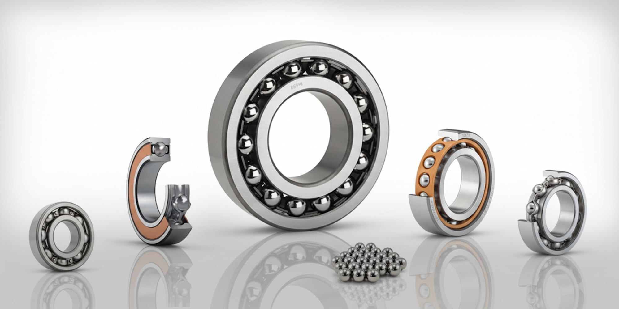
Ball bearings are the most widely used type of rolling bearings. Their primary function is to reduce friction between moving parts and support both ...