Home/
Blog/
What Is a Gear Rack? Types, Materials & How to Choose the Right One

9 min read

What Is a Gear Rack? A Complete Guide to Types, Materials & Selection

What Is a Gear Rack? A Complete Guide to Types, Materials & Selection
What Is a Gear Rack? Types, Materials & How to Choose the Right One
16:40

You’re designing a linear axis and the question comes down to drive selection: ball screw, belt, or gear rack?

For most engineers, the tipping point is travel distance and speed.

Once you’re beyond about 1.5 m of travel at meaningful load, a gear rack is almost always the more practical — and more cost-effective — answer.

But ‘gear rack’ covers a wider range of specifications than most people assume.

Tooth geometry, module, material, pressure angle, cross-section, and accuracy grade all affect how a rack performs in service.

This guide walks through each variable so you can make a confident selection.

What Is a Gear Rack?

A gear rack is a straight, toothed bar that converts rotational motion into linear motion — or vice versa — when paired with a mating pinion gear.

Unlike a ball screw or belt drive, a gear rack has no theoretical stroke limit: racks can be joined end-to-end to achieve travel distances of several meters without compromising stiffness or load capacity.

The teeth are cut at a defined pressure angle — most commonly 20° in modern industrial applications, though 14.5° remains widely used in replacement and legacy parts.

Pressure angle affects tooth strength, contact ratio, and the side load transferred to the pinion shaft bearing.

A 20° rack is generally stronger and more compact for the same load rating, which is why it has become the default for new designs.

Labeled cross-section of a gear rack showing tooth face, module pitch, tooth root, rack body, pressure angle, and mating pinion Tooth face Module pitch (= π × m) Tooth root Rack body Pressure angle 20° Mating pinion

Fig. 1 — Key components of a gear rack and its mating pinion

Gear Rack vs. Other Linear Motion Options

Before selecting a rack, it’s worth mapping it against the alternatives. Each drive type has a practical sweet spot:

Drive Type Max Speed Positioning Accuracy Stroke Limit Best For
Gear Rack Up to 10 m/s ±0.1 mm standard; ±0.01 mm precision helical Unlimited (spliced) Long-travel, high-speed axes
Ball Screw Up to 1 m/s ±0.005 mm ~4 m practical High-precision, short-to-mid travel
Belt Drive Up to 5 m/s ±0.1–0.5 mm ~10 m Light loads, high speed
Linear Motor Up to 10 m/s ±0.001 mm Unlimited Highest precision, highest cost

Main Types of Gear Rack

1. Spur Gear Rack

Spur racks have teeth cut parallel to the rack axis — the simplest geometry and the most widely produced.

They are inexpensive to manufacture, straightforward to replace, and available across the widest range of sizes, modules, and materials.

For most general-purpose linear axes running below about 1 m/s, a spur rack is the default choice and there is rarely a reason to complicate it.

Where they’re used: Drill press tables, sliding gates, packaging lines, manual positioning stages, general CNC gantries.

Limitation: Because all tooth contact happens simultaneously across the full face width, spur racks produce more noise and vibration than helical racks at higher speeds. Above roughly 1 m/s, noise and accelerated tooth wear become real operational concerns.

2. Helical Gear Rack

Helical racks have teeth cut at an angle to the rack axis — the helix angle, typically between 15° and 25°.

Because tooth contact begins at one end and progresses gradually across the face width, load is shared across multiple teeth simultaneously at any instant.

In practice, this produces measurably smoother motion, lower noise, and higher load capacity compared to a spur rack of the same module and face width.

Advantages over spur racks:

  • Smoother, quieter operation — particularly noticeable above 1 m/s
  • Higher load capacity for the same module and rack width
  • Better positional accuracy under load due to reduced effective backlash

Trade-off: The angled teeth introduce an axial thrust force component. The pinion shaft bearings must be selected and rated to handle this thrust load — an additional design consideration that adds system cost and complexity. If your bearing arrangement is already under load from other sources, factor this in early.

Where they’re used: CNC machine tool axes, gantry robots, automated storage and retrieval systems (ASRS), any application demanding smooth, consistent motion at moderate-to-high speeds.

Side-by-side view: spur rack with straight teeth on left, helical rack with angled teeth on right 0° (straight) Spur rack Teeth parallel to axis Helix angle ~20° Helical rack Teeth angled to axis

Fig. 2 — Spur rack (straight teeth) vs helical rack (angled teeth)

3. Rectangular vs. Round Cross-Section

The cross-section describes the rack body shape, not the tooth geometry:

  • Rectangular racks are the standard for most applications. They bolt flat against a mounting surface, alignment is straightforward, and mounting holes can be pre-drilled through the rack body for direct fastening.
  • Round racks (cylindrical racks) have a circular cross-section that allows the rack to be clamped and rotated to any angular position before fixing. This is useful where the rack must be oriented at a non-standard angle to the mounting surface, or where a round-bore clamping arrangement is mechanically simpler than a flat mount.

4. Metric vs. Inch

Metric and inch are measurement systems, not performance categories — but the distinction matters enormously when ordering:

  • Metric racks are defined by module (m), where pitch = π × module. Common modules: 1, 1.5, 2, 3, 4, 5, 6, 8, 10.
  • Inch racks are defined by diametral pitch (DP) — the number of teeth per inch of pitch diameter. Common DPs: 4, 6, 8, 10, 12, 16, 20.

The two systems are not interchangeable. A metric rack will not mesh correctly with an inch pinion. In North American markets both systems are actively used; metric dominates in Europe and Asia. When replacing a rack in an existing machine, confirm the system and the specific module or DP before ordering — getting this wrong is an expensive mistake.

Side-by-side comparison of metric module and inch diametral pitch with NOT interchangeable warning METRIC Defined by: Module (m) Pitch = π × m Common modules 1 · 1.5 · 2 · 3 · 4 · 5 · 6 · 8 · 10 Dominant regions Europe · Asia · Global OEM INCH Defined by: Diametral Pitch (DP) DP = teeth per inch of pitch dia. Common DPs 4 · 6 · 8 · 10 · 12 · 16 · 20 Dominant regions North America · legacy systems ⚠ NOT interchangeable

Fig. 6 — Metric module vs inch diametral pitch: two incompatible systems

Gear Rack Materials

Material choice drives load capacity, corrosion resistance, noise level, and unit cost.

In practice, most engineers default to 1045 carbon steel and only move to alloy steel or stainless when load demands or the operating environment require it.

Five gear rack materials compared across load capacity, corrosion resistance, unit cost, and best environment Material Load capacity Corrosion resist. Unit cost Environment 1045 Carbon Steel Dry industrial 4140 Alloy Steel Heavy load high cycle 304 Stainless Food / pharma / wet 416 Stainless Corrosion + load Acetal (POM) Light duty / silent = higher = lower Cost: fewer dots = lower cost

Fig. 3 — Material comparison across load, corrosion resistance, cost, and environment (● = higher rating)

Carbon Steel (1018, 1045)

The standard choice for most industrial applications. 1045 carbon steel has a tensile strength of approximately 570 MPa and handles moderate-to-heavy loads reliably in dry or lightly oiled environments.

1018 is softer and easier to machine, which is useful when racks will be cut to custom lengths on-site.

Neither grade is appropriate for wet, chemical, or food-processing environments without a protective coating.

Alloy Steel (4140)

4140 chromoly alloy steel delivers tensile strength in the range of 655–1,020 MPa depending on heat treatment — the right choice for high-load, high-cycle applications where fatigue life is a genuine concern.

Heavy gantry systems, large CNC machine axes, and industrial robotics installations are typical candidates.

The step up in material cost is justified when you’re running hard.

Stainless Steel (304, 416)

304 stainless provides solid corrosion resistance and is the standard material for food processing, pharmaceutical, and wet industrial environments.

416 stainless is a martensitic grade that machines more cleanly than 304 and can be hardened — better for applications combining corrosion resistance with higher tooth loads.

The trade-off versus carbon steel is a lower hardness ceiling, which means lower tooth surface load capacity at the same module.

Acetal Plastic (POM)

Acetal (POM) racks are self-lubricating, near-silent in operation, and chemically resistant.

They’re a sensible choice for light-duty, low-speed applications — medical devices, laboratory automation, office equipment — where a steel rack would be oversized and noise matters.

Load limits are significantly lower than steel: acetal racks should not be used where tooth loads exceed approximately 10–15% of an equivalent steel rack’s rating.

They are also sensitive to sustained temperature — under continuous load, acetal begins to creep above approximately 80°C, so verify thermal conditions at the installation point before specifying.

Black Oxide Carbon Steel

Black oxide is a conversion coating applied to carbon steel racks.

It provides mild corrosion resistance, but is typically rated for indoor, dry environments only — significantly less protection than stainless steel and not suitable for outdoor or humid conditions without supplementary lubrication.

It’s primarily specified for aesthetic uniformity or as a base for oil retention in lightly lubricated applications.

How to Select the Right Gear Rack

6-step flowchart for selecting the right gear rack with a spur vs helical decision branch at Step 3 Step 1 Define tangential load (Ft) Step 2 Choose module or diametral pitch Step 3 Speed above 1 m/s? No Spur rack Yes Helical rack Step 4 Match metric or inch system Step 5 Choose material for environment Step 6 Plan lubrication schedule

Fig. 4 — Six-step gear rack selection process

Step 1: Define the Tangential Load

Calculate the tangential force (Ft) the rack must transmit:

Ft = (2 × Torque) / (Module × Number of pinion teeth)

Apply a service factor of 1.25–2.0 depending on shock loading characteristics. This gives your minimum tooth strength requirement and is the foundation of every other selection decision.

Step 2: Choose the Module or Diametral Pitch

Larger module = larger, stronger teeth. As a working guide:

Module (metric) Typical Tangential Load
1–2 Light duty, up to ~500 N
3–4 Medium duty, 500 N–3 kN
5–8 Heavy duty, 3–15 kN
10+ Very heavy duty, 15 kN+

Always verify against the manufacturer’s rated tooth load tables, which account for material, face width, and operating speed.

Step 3: Select Tooth Geometry

  • Use spur for speeds below ~1 m/s, budget-sensitive applications, or where axial loads on pinion bearings must be minimized.
  • Use helical for speeds above 1 m/s, noise-sensitive environments, or where maximum load capacity is needed within a given rack size.
  • Use 20° pressure angle for all new designs unless you are replacing a legacy 14.5° system.

Step 4: Match the Measurement System

Confirm metric or inch, then match module or DP to your existing pinion.

If starting from scratch, select a matched rack-and-pinion set from a single manufacturer to guarantee mesh geometry — mixing components from different suppliers without verifying tooth form compatibility is a common source of field failures.

Step 5: Choose Material for the Environment

Environment Recommended Material
Dry industrial, general purpose 1045 Carbon Steel
High load / high cycle 4140 Alloy Steel
Wet / food processing / pharma 304 or 416 Stainless Steel
Light duty, low noise, low speed Acetal Plastic (POM)
Indoor dry, mild protection only Black Oxide Carbon Steel

Browse our full range of metric and inch gear racks — spur and helical, rectangular and round cross-section, in carbon steel, alloy steel, stainless, and acetal plastic, with options interchangeable with Boston and Martin gear standards.

Step 6: Plan for Lubrication

Steel racks require periodic lubrication.

A lithium-based or EP (extreme pressure) grease applied to the tooth faces every 500–1,000 operating hours is a practical baseline for most industrial applications — follow the pinion manufacturer’s specification where one exists.

Helical racks running at high speeds benefit from automatic lubrication systems to maintain consistent film thickness and prevent hot-spot wear.

Acetal racks require no lubrication; adding grease to a plastic rack attracts particulate contamination and accelerates wear rather than reducing it.

Gear Rack Accuracy Grades

Gear racks are manufactured to standardized accuracy grades defined by ISO 1328-1:2013, which classifies cylindrical gears — including racks — from Grade 1 (highest precision, tightest tolerances) to Grade 12 (lowest precision).

The American Gear Manufacturers Association (AGMA) publishes the equivalent North American standard (ANSI/AGMA 2015-1-A01) using an A2–A11 accuracy grade system, with lower numbers again indicating higher precision.

As a practical guide to ISO grade selection:

  • Grades 9–12: General-purpose commercial grade. Suitable for non-precision applications such as sliding gates, manual stages, or light conveying systems.
  • Grades 6–8: Medium precision. Suitable for most CNC and industrial automation applications.
  • Grades 3–5: High precision. Required for machine tool axes and applications where positioning error must be held below 0.02 mm per 300 mm of travel.

When matching a replacement rack to an existing system, always verify the accuracy grade.

Pairing a lower-grade rack with a higher-precision pinion concentrates tolerance error on the pinion teeth and accelerates wear on your more expensive component.

Frequently Asked Questions

Can I join two gear racks end-to-end for longer travel?

Yes — splicing is standard practice for long-travel axes. Racks are typically supplied in 500 mm, 1,000 mm, or 2,000 mm lengths specifically designed for end-to-end joining.

The critical requirement is pitch alignment at the joint: a pitch error at the splice point creates a repeatable positioning error every time the pinion crosses it.

In high-precision systems this is measured and corrected during installation rather than left to chance.

Two gear racks joined end-to-end showing the splice point and pitch alignment requirement Splice point Pitch alignment critical here Rack 1 Rack 2

Fig. 5 — End-to-end rack splicing: pitch alignment at the joint is critical

What is the difference between a gear rack and a lead screw?

A lead screw converts rotation to linear motion through helical thread engagement rather than gear teeth.

Lead screws offer higher positional accuracy per revolution but are limited in practical stroke length (typically under 2 m), maximum speed (usually below 0.5 m/s), and load capacity compared to a rack-and-pinion drive of similar diameter.

For short-travel, high-precision applications, lead screws compete seriously; beyond about 1.5 m of travel at any meaningful load, the gear rack is usually the stronger engineering choice.

How do I calculate linear speed from pinion RPM?

Use the following formula:

Linear speed (m/min) = π × Module × Number of pinion teeth × RPM ÷ 1,000

Example: a module 3 rack with a 20-tooth pinion running at 300 RPM gives π × 3 × 20 × 300 ÷ 1,000 = 56.5 m/min.

What causes premature gear rack wear?

Three causes account for the vast majority of field failures: insufficient lubrication, rack-to-pinion misalignment, and operation beyond the rated tooth load.

In most cases encountered in the field, misalignment is the primary culprit — even 0.1 mm of parallel misalignment between rack and pinion concentrates load on one edge of the tooth face, dramatically reducing fatigue life on both components.

If a rack is wearing unevenly across its face width, check alignment before assuming the load rating is insufficient.

Are metric and inch gear racks interchangeable?

No. Metric and inch racks use fundamentally different pitch definitions and will not mesh correctly with a pinion from the other system.

There is no conversion that makes them compatible — if you are replacing a rack, confirm the system (metric module or inch diametral pitch) and the exact specification before ordering.

Mating an inch pinion to a metric rack, or vice versa, will result in immediate tooth damage on first operation.


Polyurethane Rollers vs. Wheels: How to Choose

Polyurethane Rollers vs. Wheels: How to Choose

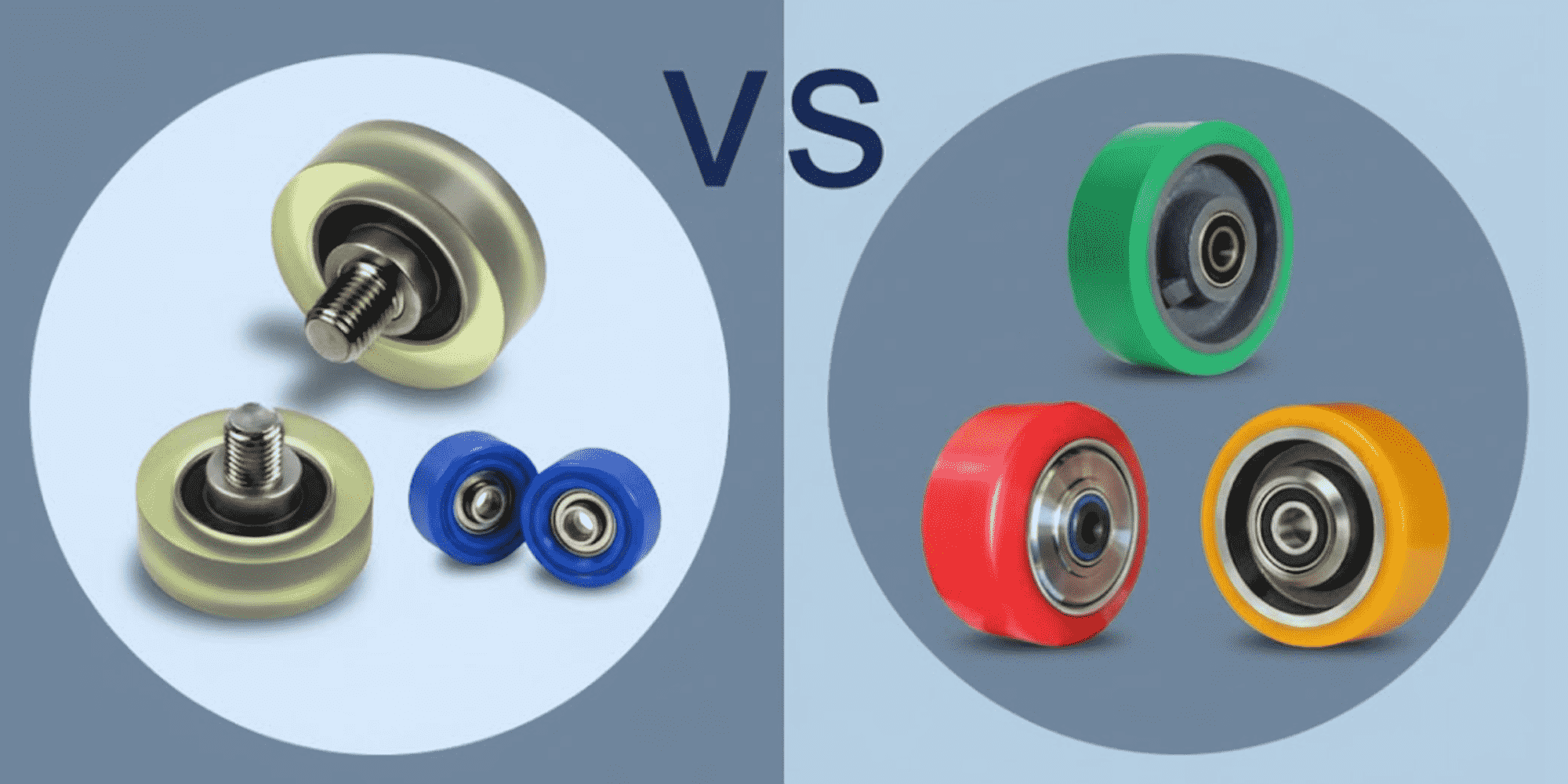
In my 15 years at LILY Bearing, I've seen one specification error cost companies $30K-50K in unplanned downtime: confusing polyurethane rollers with...

Read More
Linear Bearing Noise & Failure: Causes, Diagnosis & When to Replace

Linear Bearing Noise & Failure: Causes, Diagnosis & When to Replace

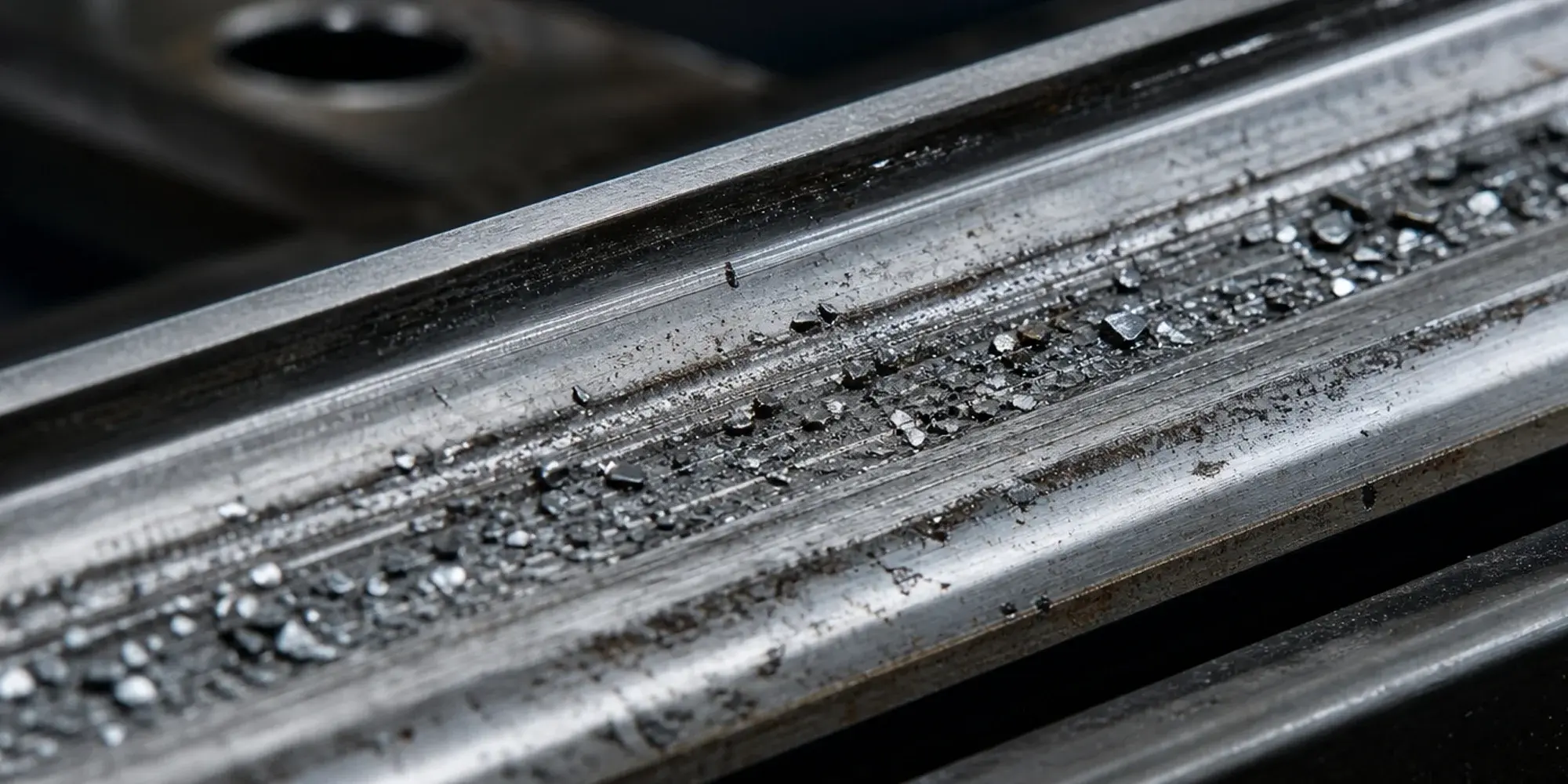
A linear bearing that's failing doesn't always give you much warning. Sometimes it starts with a subtle grinding sound at one end of the stroke. ...

Read More
Pillow Block Bearing Size Chart: How to Determine the Right Size for Your Shaft

Pillow Block Bearing Size Chart: How to Determine the Right Size for Your Shaft

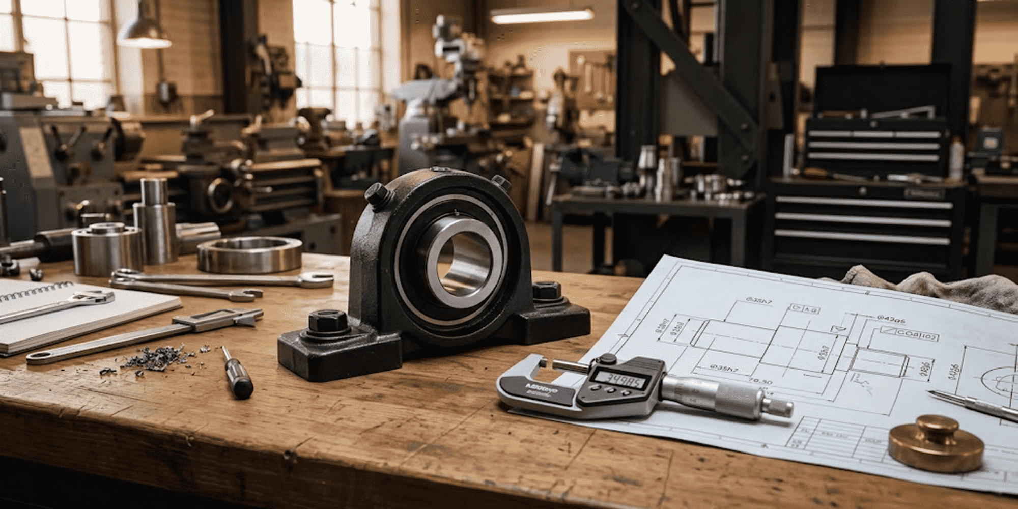
The most common sizing mistake we see: someone measures their shaft with a tape measure, rounds to the nearest half-inch, and orders the wrong bore. ...

Read More