

 Robert
How Do Gears Work? A Guide to Speed, Torque, and Gear Ratios
Why do some mechanical systems prioritize raw power while others focus on high-speed rotation? At LILY Bearing, I’ve seen how a tiny adjustment in...
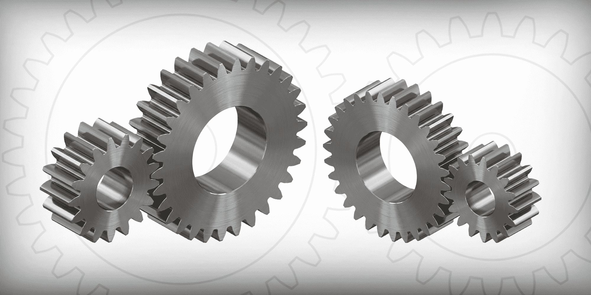
Walk into any factory, open up a household appliance, or look inside a medical device, and you'll almost certainly find a spur gear doing quiet, reliable work.
They're the most common gear type in existence — and for good reason.
Spur gears transmit motion and power between two parallel shafts using a deceptively simple principle: straight teeth, cut parallel to the axis of rotation, that mesh together to transfer torque with efficiencies typically between 95% and 99%.

But simple doesn't mean unsophisticated.
Getting a spur gear right — choosing the correct module, pressure angle, material, and manufacturing process — is what separates a drive system that performs for years from one that fails under load.
This guide walks through everything engineers and buyers need to know.
Spur gears function by meshing their teeth along a shared pitch circle — an imaginary reference circle where the tooth profiles of two mating gears effectively meet.
As the driving gear rotates, its teeth push against the teeth of the driven gear, transferring torque from one parallel shaft to another.
The tooth contact follows an involute curve profile.
This geometry ensures a constant velocity ratio as the teeth mesh: the line of force remains tangent to the base circles throughout engagement, so angular velocity stays smooth and predictable.
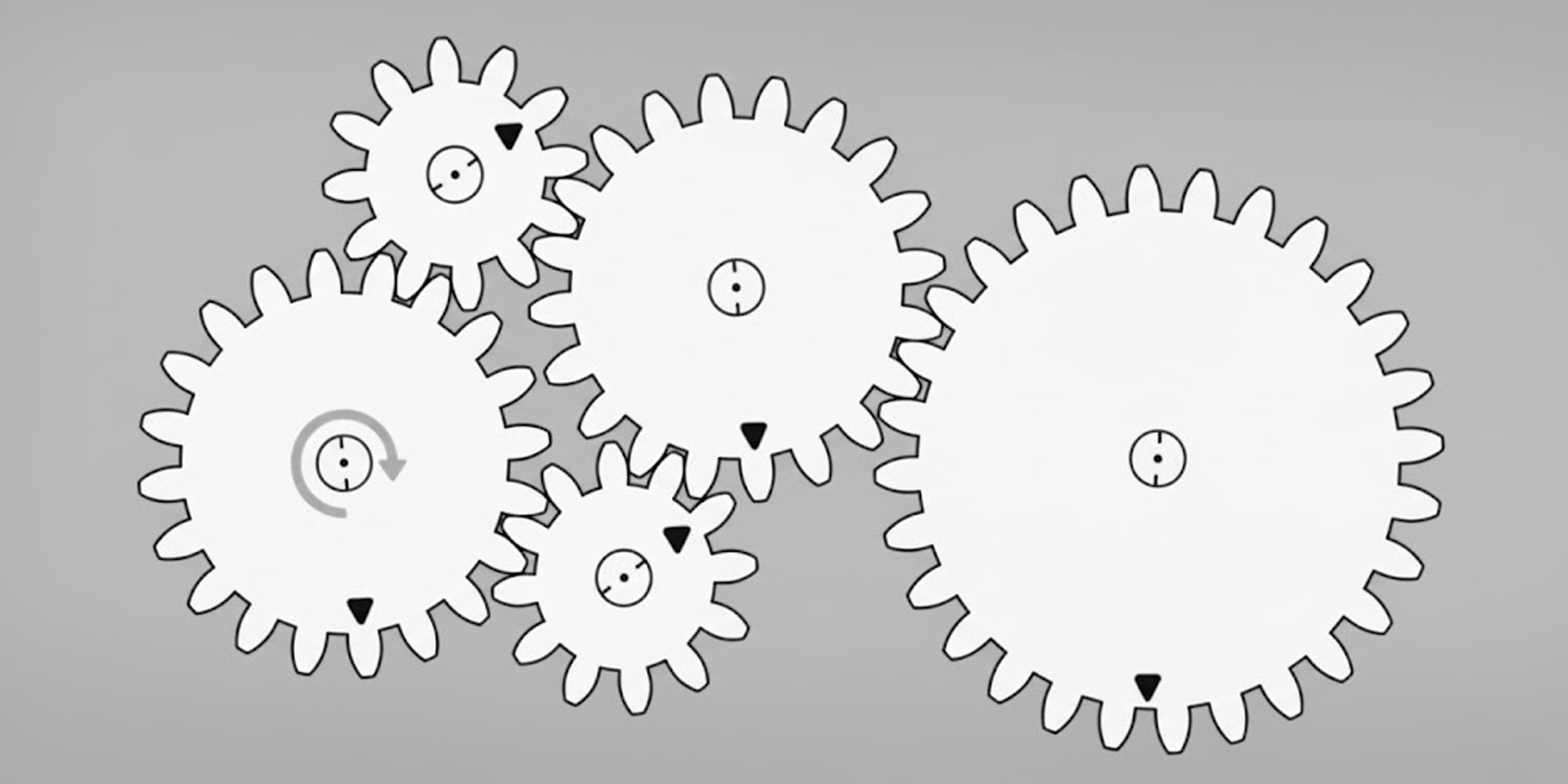
In a correctly matched pair, the driven gear always rotates in the opposite direction to the driving gear.

One practical consequence of the straight-tooth design is that spur gears generate only radial forces — there's no axial thrust pushing the gear along the shaft.
This makes mounting simpler and allows the use of standard ball bearings rather than the thrust bearings that helical gears often require.
The trade-off is noise.
Because spur gear teeth engage abruptly — one full tooth pair at a time rather than gradually — they produce more vibration and noise at high speeds than helical gears.
For most industrial applications this is perfectly acceptable, but it's why you won't find spur gears in a car's main transmission where quiet operation is a priority.
Every spur gear is defined by a precise set of geometric parameters.
Understanding these is essential when specifying, purchasing, or designing around a gear.
Tooth size is the starting point for any gear specification, and there are two systems in common use depending on geography.
In the metric system, tooth size is expressed as the module (abbreviated m). Module is defined as the pitch diameter divided by the number of teeth.
A gear with a pitch diameter of 40 mm and 20 teeth has a module of 2 mm.
As the module value increases, the tooth gets physically larger — a module 4 tooth is roughly twice the size of a module 2 tooth.
Standard metric modules range from 0.5 to 4 mm for most precision applications, extending further for heavy industrial gearing.

In the English system, tooth size is expressed as the diametral pitch (DP) — the number of teeth per inch of pitch diameter.
A gear with 24 teeth and a 2-inch pitch diameter has a DP of 12. Critically, the relationship works in reverse from module: a higher DP means a smaller tooth.
Commercial spur gears are commonly available in diametral pitches of 6 to 48 DP.
The two systems are not interchangeable; mating gears must always share the same pitch system and value.
The pressure angle defines the direction of the force between meshing gear teeth — specifically, the angle between the line of action and the tangent to the pitch circle at the point of contact.
Two values dominate industry practice.

The 14.5° pressure angle was the historical standard, favoured for quieter operation and smoother engagement.
It's still found in older equipment and replacement parts for legacy machinery.
The 20° pressure angle is now the global industry standard for new designs.
The steeper angle produces thicker, stronger tooth bases with better resistance to undercutting — particularly important when pinions have fewer than 17 teeth — and higher load-carrying capacity overall.
For metric spur gears, 20° is essentially universal.
The pitch circle is the imaginary reference circle used to establish tooth spacing and from which all tooth proportions are calculated.
The pitch diameter is the diameter of this circle and is the critical value for determining center distance between mating gears.
For standard (non-profile-shifted) gear pairs, the center distance equals half the sum of both gears' pitch diameters.

The addendum is the radial height of a tooth above the pitch circle; the dedendum is the depth of the tooth below it.
Together they determine total tooth height.
The dedendum is always slightly greater than the mating gear's addendum, providing clearance at the root to prevent jamming and allow lubrication to reach the contact zone.

Backlash — the small gap between mating teeth when they're not in contact — is often misunderstood as a defect. It's not.
A minimum amount of backlash is necessary for proper meshing, thermal expansion, and lubrication film formation.
Too little backlash leads to tooth seizure; too much increases vibration and positional error.
For precision robotics and CNC machinery where backlash is unacceptable, anti-backlash gear assemblies use a spring-loaded dual-gear mechanism to maintain zero play without causing tooth seizure.
Most engineers spec a standard spur gear (profile shift coefficient x = 0) and move on.
But profile shifting — adjusting the position of the cutting tool relative to the gear blank during hobbing — is a straightforward way to solve two common problems without changing the gear ratio.
A positive profile shift strengthens the tooth at its base (thicker root) and prevents undercutting on small pinions with fewer than 17 teeth.
A negative shift allows a modest reduction in center distance when two gears must fit within a constrained housing.
When both gears in a pair carry non-zero shift coefficients, a working pressure angle calculation is required to determine the actual center distance.
When both shift coefficients are zero, the math is simpler: center distance equals half the sum of the pitch diameters.
Profile shifted gears are particularly valuable in compact gearboxes where shaft spacing is fixed but off-the-shelf standard gears don't quite fit.
The most common configuration: teeth are cut on the outside of a cylindrical blank.

When two external gears mesh, they rotate in opposite directions.
This is the standard setup for the vast majority of power transmission applications, from conveyor drives to speed reducers.
Teeth are cut on the inside surface of a ring.
An internal gear meshes with an external pinion, and the two rotate in the same direction.

Because the shafts can be positioned very close together, internal gear arrangements are significantly more compact than equivalent external setups.
They are a core component of planetary gearboxes.
A rack is a flat, linear gear — essentially a spur gear with an infinite pitch diameter.
When a cylindrical pinion meshes with a rack, rotary motion is converted to linear motion (or vice versa).
Rack and pinion systems are fundamental to CNC machine tool slides, steering systems, and industrial actuators where precise linear positioning is needed.

A planetary system combines a central sun gear, multiple planet gears orbiting around it, and an outer ring gear (internal spur gear).

By fixing different elements of the system, a wide range of gear ratios can be achieved in a very compact, high-torque package.
Planetary drives are used in robotics, electric vehicle transmissions, wind turbine gearboxes, and servo mechanisms precisely because they deliver high power density in a small footprint.
Designed for precision positioning applications, anti-backlash gear assemblies mount two gear halves on the same hub with a torsion spring between them.

The spring continuously biases the two halves in opposite directions, keeping one face of each tooth always in contact with the mating gear.
The result is effectively zero positional play — critical for semiconductor manufacturing equipment, optical instruments, and scientific apparatus where repeatable positioning matters more than cost.
Beyond the tooth geometry, spur gears vary in how they attach to shafts.
Common configurations include:
plain bore (for custom machining),
keyway (a slot that mates with a shaft key for positive torque transmission), 
spline bore (internal splines for heavy-duty torque with some axial movement capability),
set screw (threaded hole with a screw bearing against the shaft),

and split hub (clamp-style mounting for quick repositioning). 
The right choice depends on torque magnitude, shock loading, and how frequently the gear needs to be removed.
Material choice has a direct impact on load capacity, noise, weight, corrosion resistance, and cost.
The right material for a food processing conveyor is very different from what you'd choose for an aerospace actuator.
Spur gears are produced through several processes including hobbing, gear shaping, cold forming, and precision grinding — each suited to different accuracy grades and production volumes.
For a detailed breakdown, see our guide to spur gear manufacturing processes.
Spur gears and helical gears are the two most common choices for parallel-shaft drives.
Which one fits your application depends on how much noise you can tolerate, the loads and speeds involved, and what the budget allows.
Spur gears offer higher transmission efficiency (95–99%) with zero axial thrust and lower manufacturing cost — which is why they're the standard choice across most industrial drive systems.
Helical gears run quieter and handle higher speeds and loads, but introduce axial thrust forces and come at a higher price.
For a detailed side-by-side comparison including contact ratio, durability, and application-specific recommendations, see our full guide: [Helical vs. Spur Gears: Which One to Choose].
The breadth of spur gear applications reflects both their efficiency and their adaptability across scales, from miniature instrument gears to large industrial drives.
Conveyor systems, speed reducers, gear pumps, and machine tools all rely on spur gears for their core drive trains.
In speed reducers, multiple gear pairs in series step down motor speed while multiplying torque — using one motor to drive several synchronized shafts simultaneously, reducing both cost and complexity.
Precision ground spur gears and anti-backlash gear assemblies are standard in robotic joints, CNC positioning systems, and semiconductor manufacturing equipment where repeatable positioning accuracy is critical.
Planetary gearboxes built around spur gear sets deliver high torque in the compact envelopes that robot arm joints demand.
Stainless steel spur gears (SUS303 or SUS316) are specified wherever corrosion resistance and hygienic operation matter — food processing conveyors, pharmaceutical filling machines, medical device actuators.
For applications where even stainless steel introduces contamination risk, POM or PEEK plastic gears with stainless inserts offer a corrosion-proof, self-lubricating alternative.
Washing machines, dryers, blenders, office printers, and electric hand tools all use spur gears — typically plastic or light alloy — to step down motor speed and multiply torque to the driven mechanism.
The low cost and easy manufacture of small plastic spur gears make them the default choice whenever torque loads are modest and noise is tolerable.
Rack and pinion drives convert rotary motor output to precise linear motion in CNC machine tool axes, industrial robots, elevator mechanisms, and automotive steering racks.
The constant velocity ratio of spur gears makes them particularly well-suited to positioning applications where predictable motion is more important than smoothness.
Constant velocity ratio throughout the mesh cycle
Cost-effective to manufacture, especially at scale
Wide availability in standard module and DP sizes, materials, and hub configurations
Simple to install, maintain, and replace
Suitable for high-load applications when correctly sized and hardened
Noisy at high speeds — tooth engagement is abrupt compared to helical gears
Higher tooth stress than helical gears under equivalent loads, due to lower contact ratio
Only suitable for parallel shaft arrangements
Require precise center distance — limited center-distance flexibility compared to belt drives

Backlash is inherent in standard designs; zero-backlash requires special assemblies
Choosing a spur gear for a specific application involves working through a short but important checklist:
The gear ratio determines relative tooth counts.
A 2:1 ratio means the driving gear has twice as many teeth as the driven gear (or vice versa, depending on whether you're increasing or decreasing speed).
This is the starting point for sizing both gears.
Choose based on the torque to be transmitted and the space available.
Larger modules carry more load but require more space.
Both mating gears must share the same module (or DP).
Default to 20° for new designs. Use 14.5° only when replacing gears in legacy equipment specified to that standard.
Match material to operating environment and torque requirements:
hardened carbon steel for general industrial use
stainless for corrosion resistance
aluminum for weight-sensitive applications
engineering plastic for light-duty quiet operation
For quiet, high-speed operation, specify ground gears (AGMA 6–8).
For standard industrial duty, hobbed or cold-formed gears offer the best balance of performance and cost.
Choose keyway, spline, set screw, or split hub based on torque level, shock loading, and maintenance frequency.
For standard applications, accept manufacturer standard backlash.
For precision positioning, specify anti-backlash assemblies.
If center distances are constrained, investigate profile shifting options before redesigning the housing.
Both measure tooth size in different unit systems. Module (metric) = pitch diameter in mm ÷ tooth count; diametral pitch (English) = tooth count ÷ pitch diameter in inches. Higher module = larger tooth; higher DP = smaller tooth. They are mathematically related (DP × module ≈ 25.4) but not interchangeable — mating gears must use the same system.
Straight teeth engage abruptly along a full line of contact, generating repeated impacts that produce noise and vibration.
This is inherent to the geometry. Helical gears reduce this with angled teeth that engage gradually — but introduce axial thrust forces as a trade-off.
Standard metal gears require lubrication to reduce friction, dissipate heat, and prevent wear — dry operation accelerates tooth failure.
Exception: POM (acetal) and certain nylon gears are self-lubricating and designed for dry operation, making them suitable for food processing and medical applications.
Profile shifting offsets the cutting tool during hobbing to modify tooth geometry.
Use a positive shift to prevent undercutting on small pinions (fewer than 17 teeth at 20°) or to adjust center distance within a fixed housing — without changing the gear ratio or module.
Properly lubricated spur gear pairs achieve 95–99% efficiency per mesh — among the highest of any gear type.
For multi-stage gearboxes, losses compound: two stages at 98% each deliver ~96% overall.
Choose helical gears when noise and vibration must be minimized (consumer vehicles, HVAC), loads require a higher contact ratio, or shafts are non-parallel.
For standard parallel-shaft industrial drives with reasonable noise tolerance, spur gears are simpler, more efficient, and less expensive.
Spur gears remain the default choice for parallel-shaft drives because they deliver: 95–99% efficiency, predictable performance, long service life, and manufacturing costs that scale from prototype to mass production.
Getting the design right means aligning the geometry (module, pressure angle, backlash), material, manufacturing process, and hub configuration.
Whether you're replacing a failed gear or designing a new drive train, the fundamentals covered here give you the basis to make the right call.
Why do some mechanical systems prioritize raw power while others focus on high-speed rotation? At LILY Bearing, I’ve seen how a tiny adjustment in...
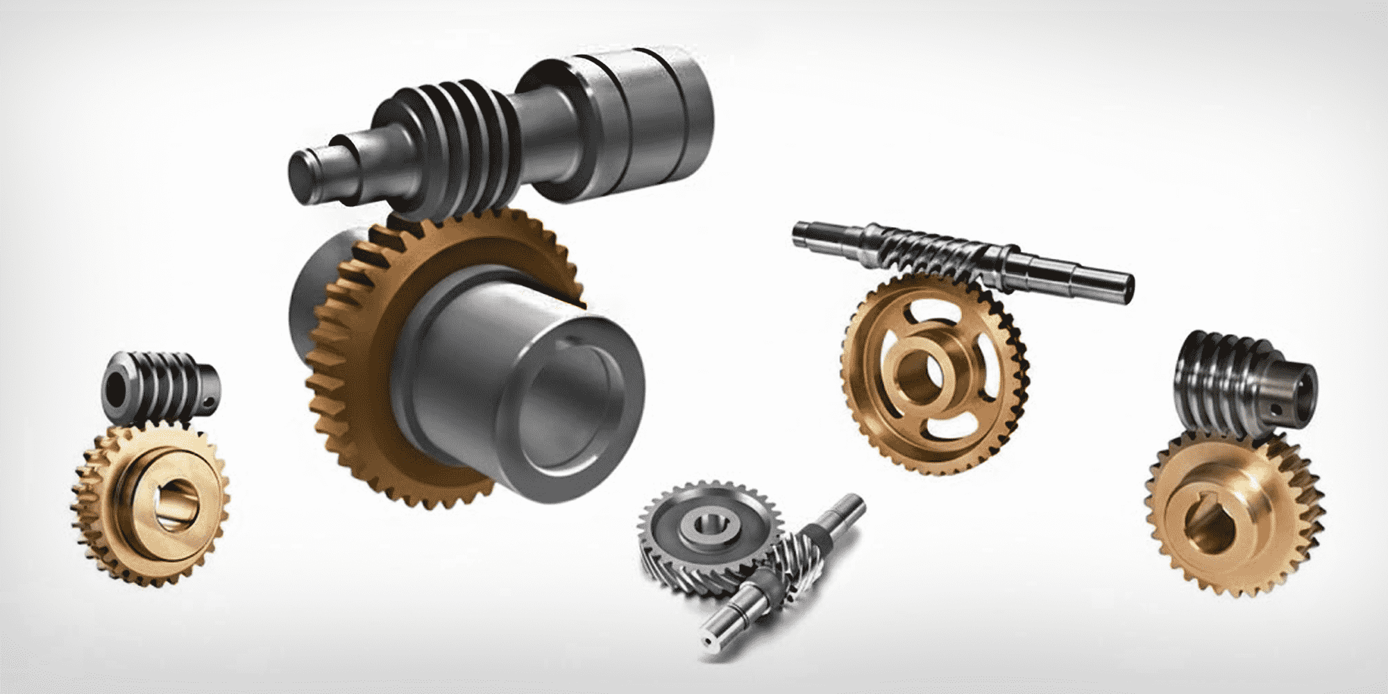
Worm gears are everywhere in daily life. You'll find them in car steering systems, conveyor belts, and stand mixers—often working invisibly behind...
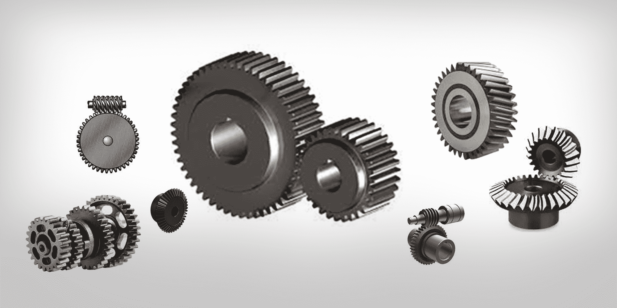
The world's leading gear manufacturers and power transmission manufacturers are the cornerstone of industrial growth, enabling everything from...