

 Robert
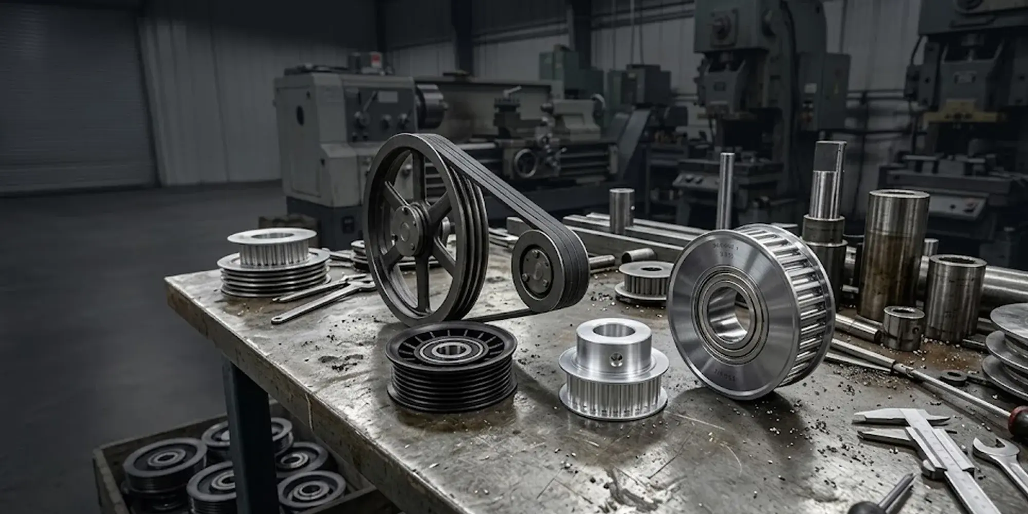
Types of Pulleys and Their Uses: Belt, Idler, Rope & Timing
A pulley is one of the six classical simple machines—but that simplicity is deceptive. In modern industrial and mechanical applications, pulleys...

In any drive system where the output shaft must rotate at a precise, predictable ratio to the input shaft—think CNC machine axes, robotic joints, automotive camshafts, or 3D printer motion systems—a timing belt pulley is not optional.
It is the only component that can deliver synchronous, slip-free power transmission with the reliability and repeatability those applications demand.
Timing belt pulleys are one of several pulley categories used in industrial drives—for an overview of how they compare to V-belt, flat belt, idler, and rope pulleys, see types of pulleys.
V-belt sheaves and flat belt pulleys rely on friction—and friction-based drives always slip, by 1–3% under normal load.
For a positioning system moving at 200 mm/s, that 1% slip translates to 2 mm of cumulative position error per second.
Timing belt pulleys eliminate that error entirely by locking belt and pulley together through tooth engagement.
This guide covers how timing belt pulleys work, the standard series and their specifications, material considerations, and a practical framework for selecting the right pulley for your application.
A timing belt pulley is a toothed wheel. Its teeth mesh precisely with the teeth molded into the inner surface of a synchronous belt.

When the drive pulley rotates, its teeth engage the belt teeth sequentially, pulling the belt and driving the driven pulley at a speed determined by the tooth count ratio—not by friction.
Because the ratio is determined by tooth count and not by pulley diameter, timing belt pulleys can achieve precise ratios—0.5:1, 1.5:1, 3.75:1—that would be impractical with a V-belt and sheave combination.
The original timing belt tooth was trapezoidal—flat-sided with angled flanks. This profile works, but stress concentrates at the tooth root under load, limiting fatigue life at high torque.
Curvilinear profiles—HTD (High Torque Drive) and the Gates GT2/GT3 standard—use a rounded tooth shape that distributes contact stress more evenly across the tooth face.
The result: 20–40% higher torque capacity for the same pitch and pulley width, with lower noise and longer belt life.
For new system designs, curvilinear profiles are the current engineering standard; trapezoidal profiles remain in use where interchangeability with legacy systems is required.
Timing belt pulleys are categorized by pitch—the center-to-center distance between adjacent teeth.
Each series is engineered for a specific power and speed range.
Using the wrong series (too small a pitch for the load) is one of the most common causes of premature timing belt failure.
The pulley material determines wear resistance, weight, corrosion performance, and cost.
Three materials cover the vast majority of applications.
Anodized aluminum pulleys offer improved surface hardness (up to 60 HRC on the anodized layer vs. ~30 HRC for untreated 6061) and better corrosion resistance than bare aluminum, at minimal weight and cost penalty.
One parameter that surprises engineers new to timing belt systems: belt tension in synchronous drives is lower than in V-belt systems.
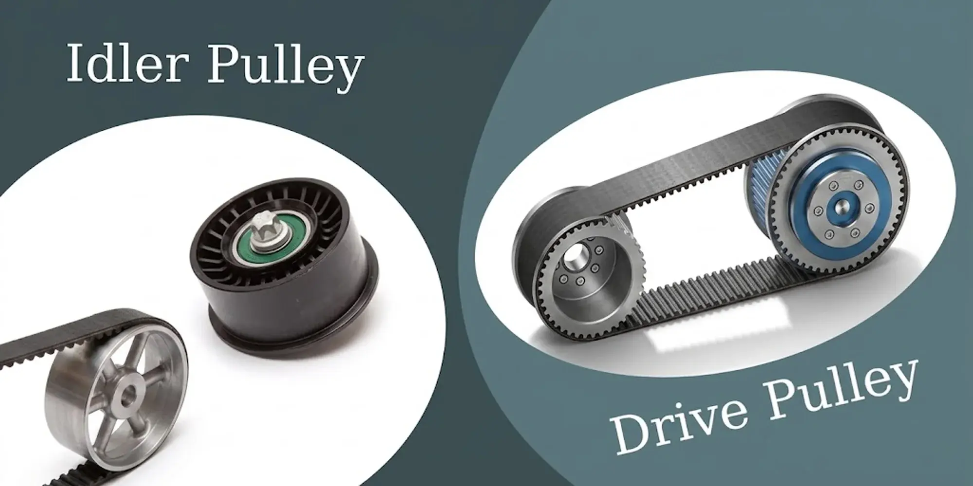
If your system also includes a tensioner or guide idler, see our guide on idler pulley vs drive pulley selection for bearing specification and failure mode reference.
Because drive force is transmitted through tooth engagement rather than friction, the belt only needs enough tension to maintain tooth mesh under load—typically 10–25% of the belt's rated tensile strength.
Over-tensioning is a common error; it accelerates bearing wear and can cause premature belt failure from tensile fatigue.
LILY Bearing
Aluminum, steel, and corrosion-resistant variants. Plain bore, keyed bore, and quick-disconnect configurations. 497 products in stock.
Shop Timing Belt Pulleys →No. XL pitch is 5.08 mm and L pitch is 9.525 mm—they are not compatible. A belt and its mating pulleys must share the same pitch. Attempting to run an XL belt on an L pulley will result in immediate tooth skipping and belt damage.
Pitch diameter (PD) = (Number of teeth × Pitch) / π. Example: a 20-tooth XL pulley has PD = (20 × 5.08) / 3.14159 = 32.36 mm. Note that pitch diameter differs from outside diameter—the OD is slightly smaller, depending on tooth height.
A quick-disconnect (QD) pulley uses a split taper bushing that locks onto the shaft with socket-head cap screws. The bushing can be removed by reversing the screws to jack it out of the bore—no shaft disassembly required. This reduces pulley replacement time from hours to minutes in multi-pulley systems.
XL uses a trapezoidal tooth profile. HTD (High Torque Drive) uses a semicircular curvilinear profile that distributes contact stress more evenly. HTD pulleys can handle 20–40% more torque than trapezoidal equivalents at the same pitch. XL and HTD belts and pulleys are not interchangeable even if nominal pitch is similar.
A properly tensioned timing belt should deflect approximately 1/64" (0.4 mm) per inch of span when a light force (typically 0.5–2 kg depending on belt size) is applied perpendicular to the span. For critical applications, a belt frequency meter matched to manufacturer tension specifications is the most accurate method.
References
ANSI/RMA IP-24 – Narrow V-Belt Drives (service factor methodology reference)
NIST – National Institute of Standards and Technology (engineering standards reference)
Norton, R.L. Machine Design: An Integrated Approach, 5th ed. Pearson.
A pulley is one of the six classical simple machines—but that simplicity is deceptive. In modern industrial and mechanical applications, pulleys...
Open any belt-driven machine—an automotive engine, an industrial conveyor, a CNC router—and you'll find at least one pulley that spins without being...
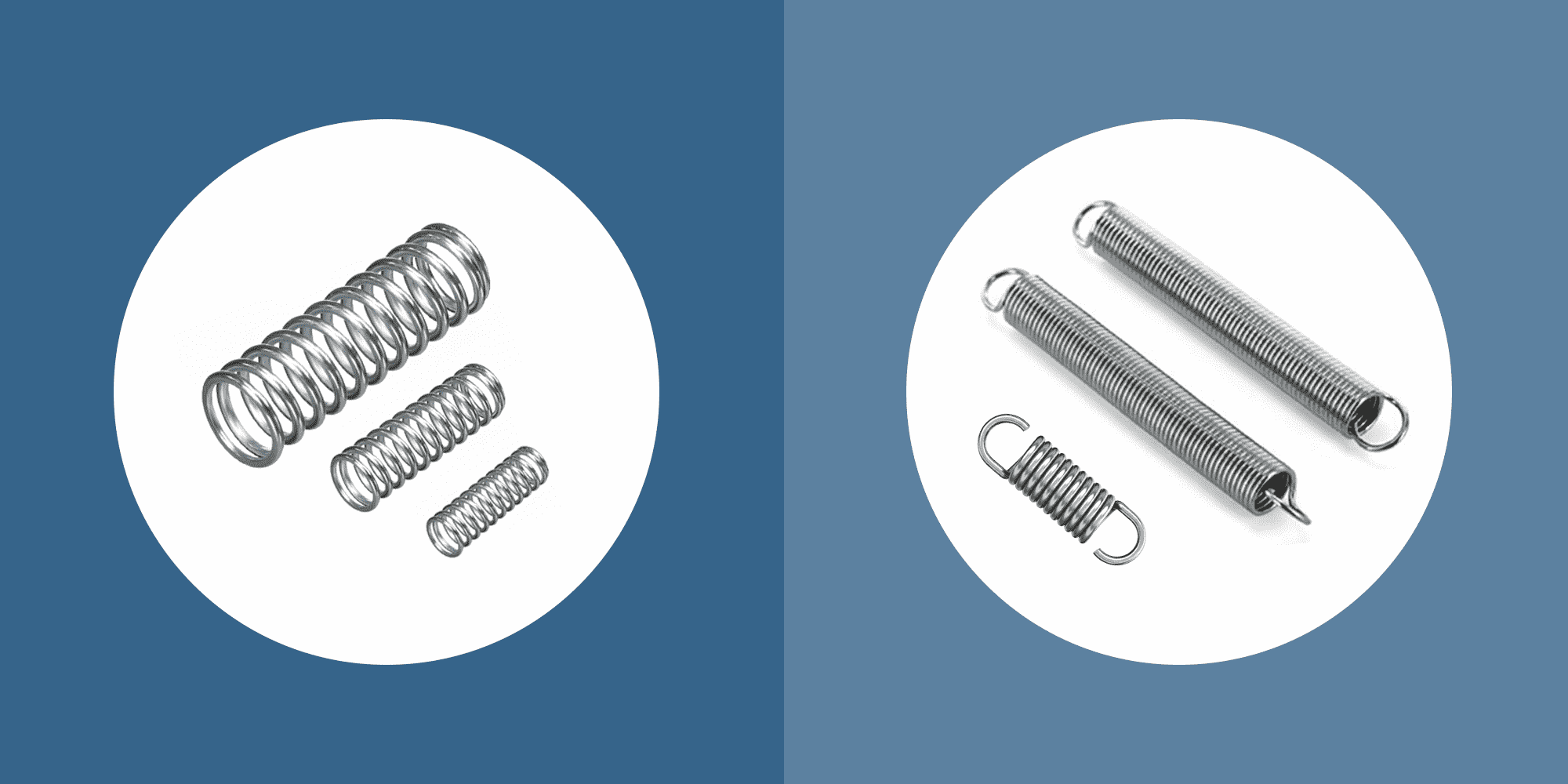
Compression vs. extension springs? One pushes, one pulls. Both store and release mechanical energy—just in different directions. Selecting the...