

 Richard
What Are Coated Bearings?
To improve their performance and service life, coatings are applied to these bearings, creating what we know as coated bearings. This blog explores...
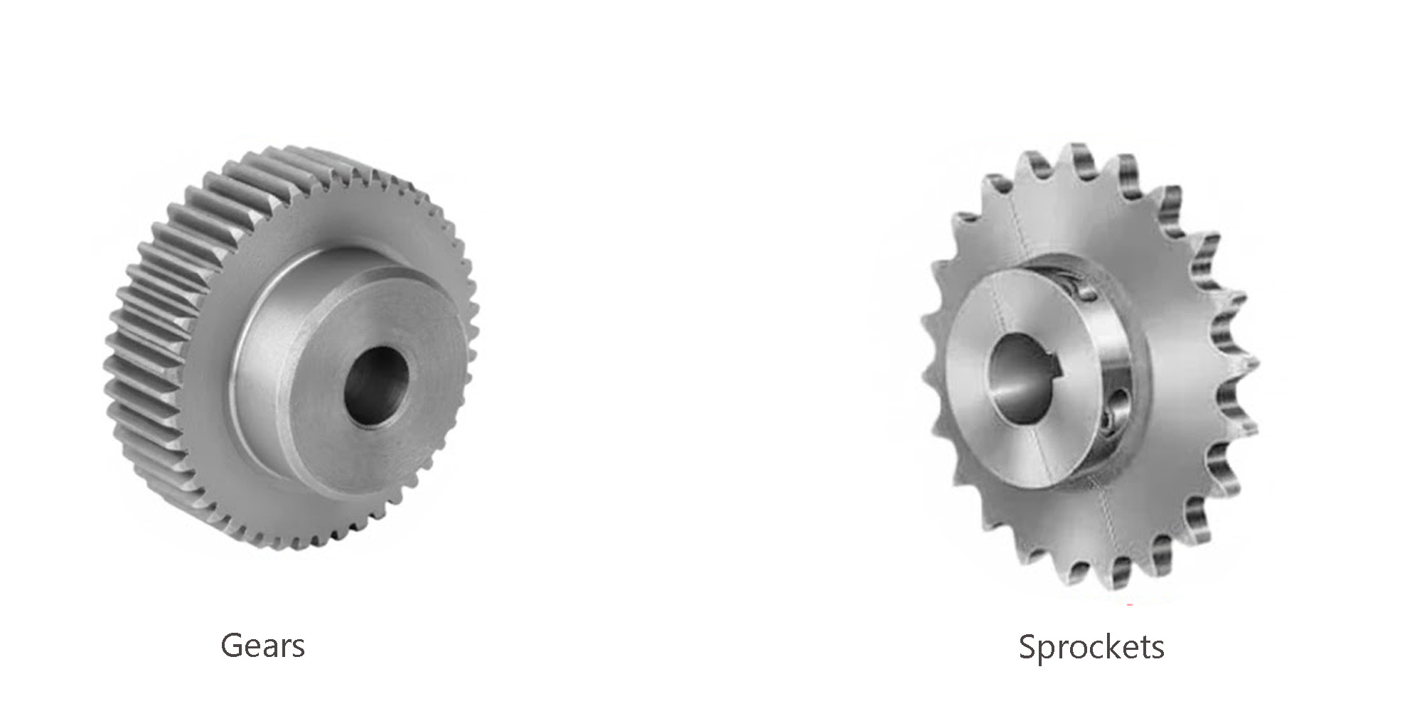
A common and confusing question arises when people ask about the difference between gears and sprockets. Many think they are the same or just call them wheels with teeth because they look similar. But if you look closely, you’ll see there are several clear differences.
The main difference between a sprocket and a gear lies in how they work. Both are grooved wheels used in machines and look quite similar, but their functions and ways of operation are not the same.
Sprockets are strong, toothed wheels designed to engage with a chain. As the sprocket rotates, its teeth catch the chain and drive the connected components. This continuous motion enables smooth and precise rotation in large machines and equipment.
Sprockets are usually made from metal or tough reinforced plastic that can handle the force needed to drive a chain. They are often compared to gears because both have a wheel-like shape with teeth.
Unlike gears that connect directly to each other, sprockets work only with chains. Most sprocket-and-chain systems work like a bicycle sprocket chain drive — a simple version of the same idea.
Sprockets are precision-engineered components designed to fit specific chains and support particular load requirements. They must adhere to strict specifications that consider factors such as size, dimensions, diameter, and teeth width and depth.
For a deeper dive into their types, uses, and how to select them, explore our comprehensive guide: What is a Sprocket?

sprockets come with different types of hubs. A hub is the thicker section around the sprocket’s center plate, excluding the teeth. According to the American National Standards Institute (ANSI), there are four primary sprocket types:
For a chain, the pitch is the distance from the center of one roller pin to the center of the next. It shows the spacing between connected points along the chain.
For the Sprocket: Sprocket diameters are measured three ways
Strands refer to the rows of teeth around a sprocket’s circumference. Most sprockets have a single strand, while some feature double or triple strands that can engage two or three chains simultaneously. Multi-strand sprockets allow a common central shaft to transmit higher torque and power.
When replacing sprockets, the caliper diameter is similar to the bottom diameter. This is measured across the sprocket’s plate, not including the teeth. For sprockets with worn or broken teeth, this measurement may be the only way to determine the sprocket’s size.
The hub diameter shows how thick the hub is. This is the extra material around the center hole of the plate on Type B and Type C sprockets.
This refers to the thickness of the sprocket. For Type C sprockets, measure from the outer edge of one hub to the outer edge of the other hub. Do this through the central hole. For Type B sprockets, the Length-Through-Bore (LTB) is measured from the outer edge of the hub to the outer edge on the opposite side of the plate.
For Type A sprockets, the LTB is simply the thickness of the plate through the bore. This measurement relates to—or is determined by—the length of the rotating shaft. Generally, a larger LTB indicates greater durability.
Sprockets can have wide or narrow teeth depending on the chain pitch they are designed to match. Chains with a larger pitch diameter need sprockets with bigger teeth. Chains with shorter distances between roller-pin centers need smaller teeth. Tooth pitch refers to the number of teeth per inch.
The sprocket bore is the central hole through which the drive shaft passes. Knowing the shaft diameter ensures that the chosen sprocket fits properly, preventing issues like tilting or slipping.
Sprocket systems are mainly used for long-distance applications. They are flexible, cost-effective, and usually work at low to moderate speeds.
Gears are rotating machine components with teeth that mesh with other gears or toothed parts to transmit torque and rotational motion. They play a key role in mechanical systems by transferring power between shafts at different speeds and torque levels.
This type of gear is designed to change the force and rotational speed of shafts by varying the gear’s radius. It has straight teeth, which is why it is called a spur gear. It is usually placed on parallel shafts. The teeth of one gear fit directly with the teeth of another gear.
Spur gears are widely available and relatively inexpensive because they are simple to manufacture. However, they tend to generate noise during operation.
Despite that, they are compact, easy to install, and highly reliable. Spur gears are good at transmitting power. They lose little energy, which makes them great for high energy transfer tasks.
They are used in a wide range of machines, including marine and automotive engines, watches, washing machines, steel mills, and trains. In mechanical watches, for example, spur gears help regulate the relative movement of the seconds, minutes, and hour hands.
Nowadays, these gears can also be produced through 3D printing, which helps reduce manufacturing costs.

Helical gears have angled teeth. These teeth are not parallel to the gear axis. This angled orientation creates a defined angle between the axis and the tooth line.
One major advantage of helical gears is that the teeth connect slowly. They do not touch all at once. This reduces impact and significantly lowers noise during operation. As a result, helical gears run more quietly than spur gears.
Helical gears can handle heavier loads than gears of the same width. Their angled teeth are longer. This allows for more surface contact. It also provides better strength at higher speeds and forces.
Helical gears are used in many industries. These include automotive gearboxes, steel production, railway systems, and food processing. They are chosen for high loads, high speeds, and quieter operation. If minimizing noise is a key design goal, a helical gear is the preferred choice.

This type of gear has a cone shape. It needs careful handling because its angle can cause jamming or misalignment. Proper fitting is essential to prevent these issues.
The main advantage of bevel gears is that they can change the direction and force of rotation. This allows power to be transmitted between shafts that are at different angles. However, bevel gears demand high assembly precision due to their complex geometry.
Because the teeth of bevel gears engage one at a time, the impact during operation can cause rough motion and gradual wear. If these gears are not made or aligned correctly, they can be harder to produce and maintain than cylindrical gears.
Another limitation is that bevel gears cannot handle high speeds or heavy loads. This is because their teeth are not parallel to the teeth of the other gear.
Spur bevel gears come in various sizes and are used in many types of machinery. Therefore, selecting the correct size and specifications for the intended application is essential.

The helical bevel gear, like the helical cylindrical gear, differs clearly from the straight-tooth version. Its slanted, elongated teeth allow for better energy utilization within the gear system, improving efficiency while reducing noise.
Because of its helical design, this gear can handle high loads and high speeds. So, it should be made from materials that can handle the impact between gears. This will ensure safety and durability.
Helical bevel gears are commonly used in machinery designed for heavy-duty applications. They are ideal for transmissions that require both high load capacity and high-speed operation.

Hypoid gears are a special type of bevel gear with unique advantages. Their key feature is that the gear shafts are offset, meaning the axis lines do not intersect. This offset design lets you position the secondary shaft more flexibly. This makes hypoid gears smaller and perfect for tight spaces.
Another benefit is their longer teeth, which provide greater contact area between gears. This allows hypoid gears to transmit more torque than standard helical gears of the same size.
However, because the shafts are separated, the teeth experience more sliding friction, which generates additional heat. As a result, high-viscosity lubricating oils must be used and reapplied regularly. Therefore, hypoid gears require special maintenance and careful lubrication to ensure reliable operation.

Spiral bevel gears are designed with slanted, curved, spiral-shaped teeth. They have the main features of bevel gears. These include strong load capacity, quiet operation, and efficient power transmission. They also provide even better performance.
Their special design lets them work well at high speeds (RPM) without big problems. This makes them perfect for jobs that need speed and accuracy, like in the automotive industry.
Spiral bevel gears are especially useful when there is a need to change the direction of rotation between shafts. The angled and curved tooth design spreads pressure evenly. This ensures smooth engagement and adaptability in many types of machines.
Spiral bevel gears have complex tooth shapes. This makes them costly to produce and often custom-made for specific uses.
They are commonly used in food processing machines, car engines, oil industry tools, and mining machines. They often work with helical and hypoid gears, where durability and performance are important.

The worm gear operates differently from other types of gears.
This mechanism consists of a worm (a threaded shaft) that meshes with another gear—often a spur gear. When the worm rotates, it drives the other gear, but at a much lower speed.
Because of this, worm gears are commonly used in applications that require significant speed reduction. Typical reduction ratios range from 1:20 to greater than 1:300, making them ideal for systems that need high torque at low speeds.
Worm gears have a special feature called self-locking. The worm can easily turn the gear, but the gear cannot turn the worm. This makes them useful in machines like conveyors. The self-locking function works as a brake when the gear motor is off.

A planetary gearbox system typically consists of four main components: a sun gear, three planet gears that revolve around it, a ring gear, and a carrier that supports the planet gears.
This setup takes the high speed from an engine and turns it into high torque. It efficiently improves power transfer by using the gears.
Compared to other gear types, planetary gears offer several advantages. They are compact, lightweight, and highly durable, delivering impressive power density relative to their size and weight.
They are great for tasks that need high reduction ratios. Planetary gear systems can reduce speed a lot while working smoothly and efficiently.
Planetary gears are commonly used in car transmissions, industrial machines, wind turbines, paper feeders, and electric motors. They are important for controlled torque and a compact design.

Rack and pinion gears form a simple yet versatile mechanism used in a wide range of applications.
The system consists of a cylindrical gear—often with straight or helical teeth—meshed with a linear gear known as a rack. The two shapes work together. They can change rotary motion into linear motion or vice versa. This depends on how the system is designed.
Rack pinion mechanisms are often used in systems that need manual or controlled operation. In these systems, the gear's movement can be started or stopped as needed.
Typical applications include automotive steering systems, automatic sliding gates, railway mechanisms for traversing steep gradients, and industrial machinery. They are also found in construction elevators, where they facilitate the vertical movement of people and materials.
Rack and pinion gears are simple but very important in many industries. They provide a reliable and efficient way to control motion.

gears are primarily used in applications that demand high precision, high torque, and a compact design
Key Differences Between Sprockets and Gears
|
Features |
Sprocket |
Gear |
|
Tooth Shape |
Three-arc straight-line shape |
Involute shape |
|
Transmission Type |
Works with chains |
Direct meshing |
|
Axle Configuration |
Parallel shafts only |
Parallel and non-parallel shafts |
|
Load Capacity |
Suitable for lower loads |
Handles higher torque and loads |
|
Speed |
Better for low to moderate speeds |
Suitable for high-speed applications |
|
Precision |
Less precision |
High precision, minimal backlash |
|
Efficiency |
Slight energy loss due to chain friction |
More efficient due to contact |
|
Durability & Wear |
Chain elongation over time, requires maintenance |
More durable but need lubrication |
.jpg?width=1024&height=401&name=unnamed%20(2).jpg)
Gears and sprockets can be combined in a mechanical system to control motion, transmit power, and adjust speed or torque.
Gears mesh directly with other gears, while sprockets work with chains. Using them together enables more complex ways to transfer power.
The most common example of gears and sprockets working together is found in a bicycle drive system:
A larger front sprocket or a smaller rear gear/sprocket raises the gear ratio. This leads to higher speed but less torque. Less torque means the rider needs to put in more effort.
A smaller front sprocket or a larger rear gear/sprocket lowers the gear ratio. This results in a slower speed but more torque. More torque makes it easier to climb hills.
Sprockets function by meshing with a chain to transfer rotational motion. As the sprocket turns, its teeth drive the chain forward, forming a continuous loop that delivers power. This interaction plays a vital role in ensuring efficient machine operation.
The sprocket’s design—such as its tooth count and pitch spacing—determines the smoothness of chain movement and the amount of power transmitted. To maintain peak performance, the sprocket and chain system must be properly aligned and regularly maintained.
In summary, understanding the distinction between sprockets and gears is key for anyone working with mechanical systems. While both are vital for power transmission, each operates in its own way and serves specific functions.
With this knowledge, you can better identify how gears and sprockets complement each other and make informed choices for efficient system design and maintenance.
Explore the full range of sprockets and gears at lily bearing and find the perfect solution for your needs today.
To improve their performance and service life, coatings are applied to these bearings, creating what we know as coated bearings. This blog explores...
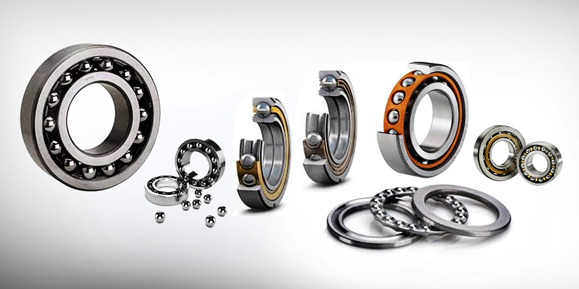
What is a ball bearing? A ball bearing is a type of rolling-element bearing that utilizes balls to maintain separation between the bearing races. The...
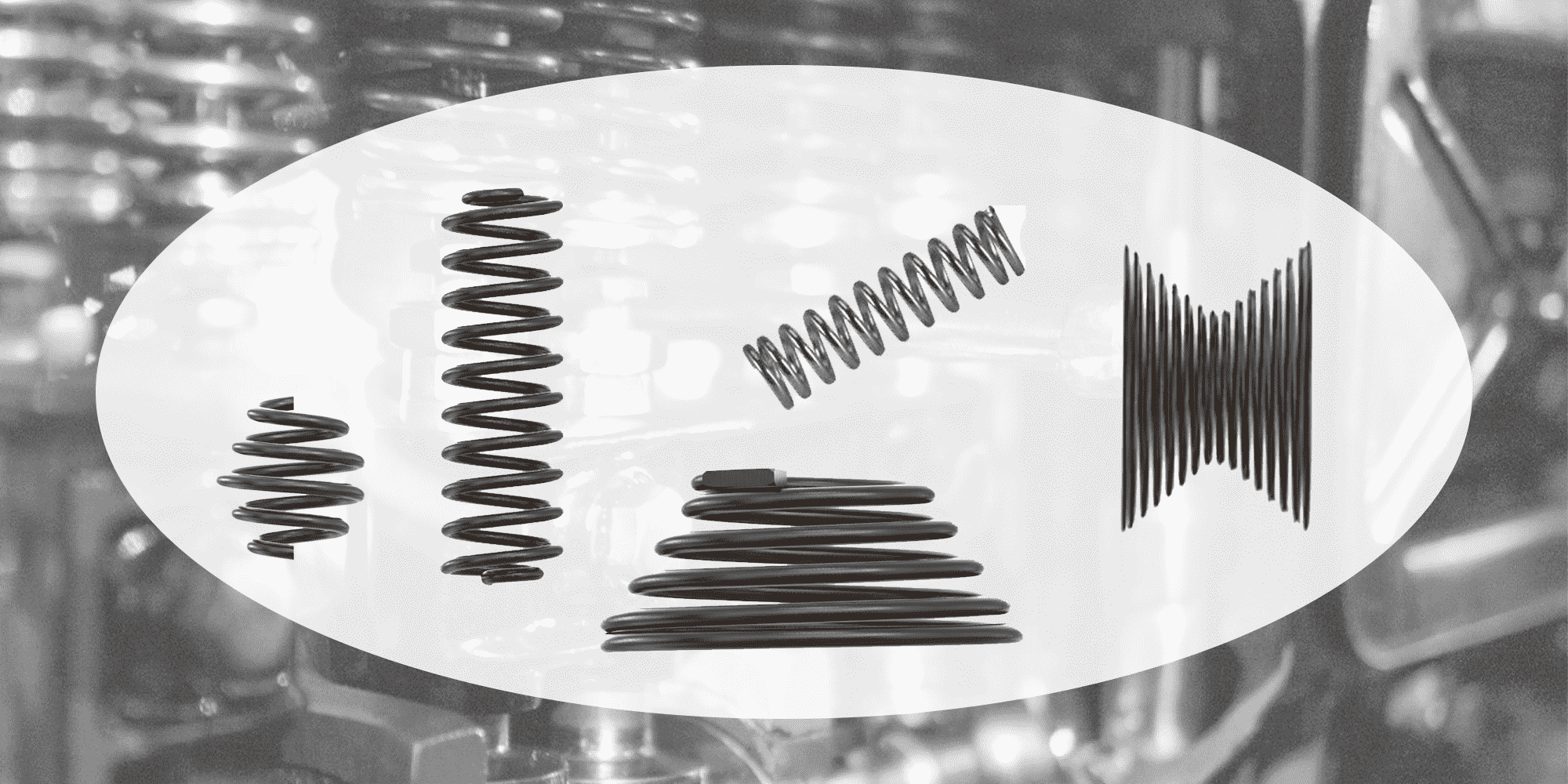
When you think of a "spring," the image that likely comes to mind is a compression spring. As the most common type of metal spring, these devices are...