

 Richard
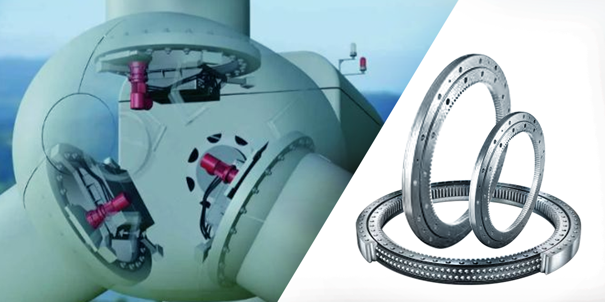
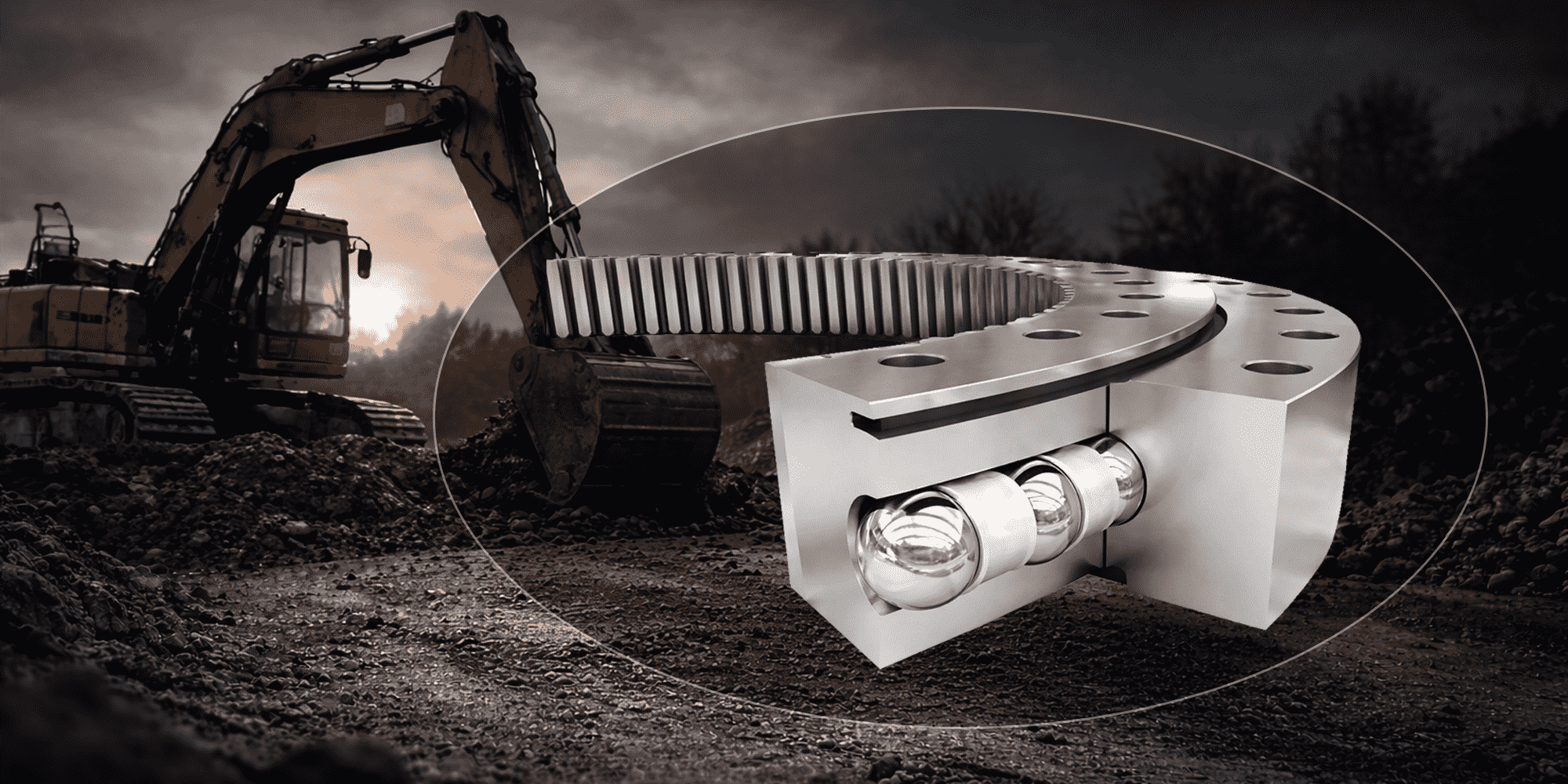
Double-row Four-point Contact Ball Slewing Bearings Well Fostered Wind Turbines
As a major bearing manufacturer in China bearing industry, Lily Bearing is well-known for developing all sorts of sophisticated slewing bearings, one...
Wind turbines depend on precise, reliable rotation at every level — from individual blade angle adjustments to full nacelle orientation.
The component that makes this possible is the slewing bearing.
Without it, a wind turbine cannot track the wind, control its blades, or convert wind energy into electricity efficiently.
This guide covers everything engineers, procurement teams, and maintenance professionals need to know about wind turbine slewing bearings: the two critical positions they occupy, the types used in each, key specifications, and how to select and maintain them for a 20-year service life.
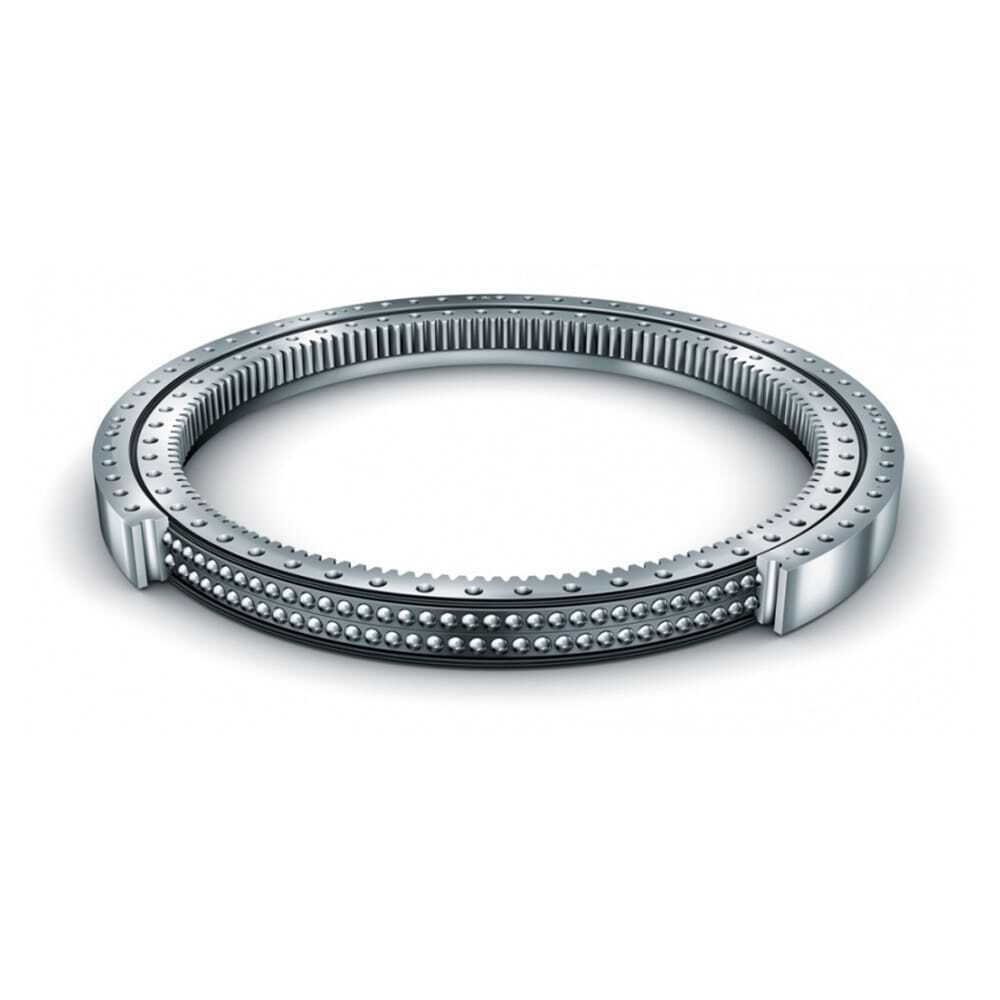
A wind turbine slewing bearing — also called a wind power bearing or large-diameter slewing ring — is a heavy-duty rotational bearing designed to handle simultaneous axial, radial, and moment loads while enabling slow, precise oscillatory movement.
Unlike standard bearings that rotate continuously at speed, wind turbine slewing bearings operate at very low speeds — typically under 2 rpm — but under enormous and constantly varying loads.
A single rotor blade can exceed 60 metres in length and weigh around 20 tonnes.
The slewing bearings at the base of each blade must absorb those forces while still allowing precise pitch angle adjustments, often multiple times per minute.
Wind turbines use slewing rings in two positions — pitch and yaw — and the requirements at each could hardly be more different.
Pitch bearings are installed at the connection between each rotor blade root and the hub.
A standard three-blade wind turbine uses three pitch bearings — one per blade.
Bearing diameters range from around 1.5 metres on smaller onshore turbines to over 3 metres on large offshore machines, sized to match the blade root diameter.
Their function is to rotate each blade around its longitudinal axis, adjusting the blade angle (pitch angle) in response to changing wind speeds.
At low wind speeds, blades are pitched to capture maximum wind energy.
As wind speed increases beyond the turbine's rated capacity, blades are progressively feathered to limit power output and protect the structure from overloading.
In emergency stop situations, blades must pitch to a fully feathered position within seconds.
Pitch bearings experience complex, asymmetric load patterns — the load on a blade varies significantly depending on its position in the rotor sweep (upward vs. downward).
This makes pitch bearing fatigue life calculation significantly more demanding than for standard rotating bearings, and is governed by NREL Design Guideline DG03 for Yaw and Pitch Bearings.
Most common type: Double-row four-point contact ball slewing bearing
Material: 42CrMo alloy steel — after overall quench-and-temper treatment, ring hardness reaches 229–269 HB; raceway surface induction hardening achieves 55–62 HRC
Required service life: 20 years, matching the wind turbine's designed operational lifespan
The yaw bearing is installed at the junction between the tower top and the nacelle — the housing that contains the gearbox, generator, and drivetrain.
Each wind turbine uses one yaw bearing.
Its function is to rotate the entire nacelle around the vertical tower axis, continuously aligning the rotor with the incoming wind direction.
Wind direction sensors feed data to the yaw control system, which activates yaw drives to reorient the nacelle.
Precise yaw alignment directly determines how much wind energy the rotor intercepts — misalignment of even a few degrees reduces energy capture measurably.
Yaw bearings carry the full weight of the nacelle, hub, and blades — a combined load that can exceed several hundred tonnes on large offshore turbines.
They must also withstand significant tilting moments generated by the asymmetric wind loading on the rotor disc.
Most common type: Single-row four-point contact ball slewing bearing
Material: 42CrMo alloy steel, base hardness 229–269 HB after overall tempering
Required service life: 20 years
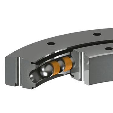
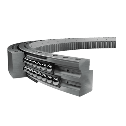
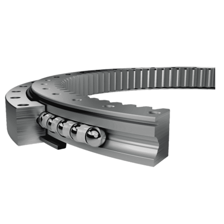
The four-point contact design — where each ball makes contact with the raceway at four points — is the dominant configuration for both pitch and yaw applications.
This design handles combined axial, radial, and moment loads in a compact single-row format.
Compactness matters here — space at both the blade root and nacelle-tower interface is limited.
When there are no loads or only pure radial loads, four-point contact occurs between the balls and inner and outer raceways.
When axial loads or overturning moments are applied, the balls shift to two-point contact with the raceways.
This load-adaptive behavior makes four-point contact bearings particularly well-suited to the variable, asymmetric loading patterns of wind turbine pitch systems.
Double-row variants provide higher load capacity and are the standard choice for pitch bearings on medium to large turbines, where the asymmetric blade loading demands greater stiffness and moment capacity.
Zero clearance — or a small negative clearance — is specified for pitch applications to reduce bearing wear under high-frequency blade vibration.
Crossed roller slewing bearings — where cylindrical rollers alternate in orientation at 90° — offer higher rigidity and precision than ball designs.
They are used in some yaw applications and in turbines where tighter rotational accuracy is required.
Their higher manufacturing cost limits their use to applications where the performance benefit justifies the investment.
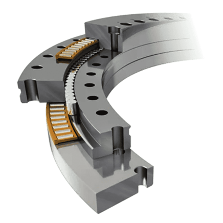
Three-row roller bearings handle axial, radial, and moment loads through three separate rows of rollers, each optimised for a different load direction.
This design provides the highest load capacity among slewing bearing types and is used as the main shaft bearing in large direct-drive turbines, where rotor diameters exceed 100 metres, blade lengths reach 75 metres or more, and bearing diameters can reach 6 metres.
If you are also evaluating slewing bearings for other heavy equipment applications, our crane slewing bearing guide covers the selection criteria for lifting and construction machinery.
Selecting the correct slewing bearing for a wind turbine application requires careful attention to the following parameters:
Pitch bearing diameters are determined by the blade root diameter, typically ranging from 1.5 metres on smaller turbines to over 3 metres on large offshore machines.
Yaw bearing diameters are set by the tower top diameter.
Large-diameter slewing bearings for wind turbines can reach 6 metres or more for rotor shaft applications.
Both static and dynamic load ratings must account for the full range of operating conditions, including extreme wind events and emergency stop loads.
The fatigue load limit — the load below which bearing fatigue damage is negligible — is particularly important for oscillating pitch and yaw applications where the bearing never completes full rotations.
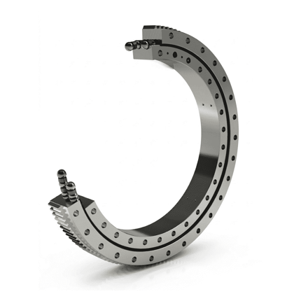
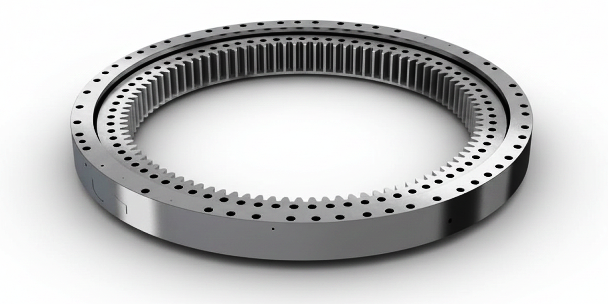
Most pitch and yaw bearings feature internal or external gear teeth that engage with the pitch or yaw drive motors.
Electrical pitch systems use gear-driven bearings; hydraulic pitch systems may use gearless bearings.
Gear module and tooth profile must match the drive system precisely.
Wind turbines operate in widely varying climates.
Bearings for cold-climate installations must be validated for extreme low temperatures — some onshore installations experience ambient temperatures as low as -40°C, with working temperatures down to -20°C.
Material selection and heat treatment must account for impact resistance at low temperatures, not just load capacity under normal conditions.
Wind turbine slewing bearings require robust sealing systems to exclude water, dust, and contaminants.
Offshore turbines demand enhanced corrosion-resistant coatings and sealing systems capable of withstanding salt spray and humidity over the full 20-year service life.
For a detailed discussion of anti-corrosion solutions for offshore and underwater applications, see our offshore slewing bearing guide.
42CrMo alloy steel with induction-hardened raceways is the industry standard.
After overall quench-and-temper treatment, ring hardness reaches 229–269 HB — sufficient to withstand shock loads without deformation.
Raceway surface hardening achieves 55–62 HRC, providing the wear resistance needed for 20-year service life under continuous oscillatory loading.
Research on slewing bearing fatigue life confirms that raceway hardening consistency is a primary determinant of service life in wind turbine applications.
Field data on wind turbine main bearings indicates that up to 30% of bearings in some turbine configurations require replacement before their designed 20-year life — at significant cost and downtime, particularly for offshore installations where access is difficult and expensive.
The most common causes of premature failure are:
The slow oscillatory motion of pitch and yaw bearings means conventional full-rotation lubrication film theory does not apply.
Lubricant films between rolling elements and raceways are thinner than in continuously rotating bearings, increasing metal-to-metal contact and accelerating wear.
Lubrication intervals and grease specifications must be tailored specifically to oscillating bearing applications.
Pitch bearings experience heavily non-uniform load distribution around their circumference.
Consistently operating with the blade in the same position concentrates fatigue damage on a small arc of the raceway.
Individual pitch control (IPC) — adjusting each blade independently — distributes wear more evenly and extends bearing life.
Misalignment during installation creates uneven stress distribution that accelerates fatigue.
Bolt torque must be applied in a specific sequence and to precise specifications — loose bolts under dynamic loads escalate rapidly.
Seal failure allows moisture and particulates to enter the bearing cavity, forming abrasive contamination that degrades raceways.
In offshore environments, saltwater ingress is particularly destructive.
Replacement costs offshore can easily exceed the bearing's original price several times over — crane hire, vessel access, and downtime all stack up fast.
This is where maintenance discipline separates reliable turbines from problem assets.
For a comprehensive guide covering all slewing bearing types, see our slewing ring maintenance guide. For wind turbine applications specifically:
Follow the turbine manufacturer's greasing schedule precisely.
Unlike excavator slew rings which require greasing every 100 hours under normal conditions, wind turbine pitch and yaw bearings have application-specific intervals based on oscillation cycles rather than operating hours.
Grease must be suitable for oscillating bearing applications — standard EP-2 grease may not provide adequate film thickness under the slow oscillatory conditions.
Check mounting bolt torque at specified intervals.
Dynamic loads on pitch and yaw bearings are severe — bolt loosening under these conditions escalates quickly and risks catastrophic failure.
Modern wind turbines increasingly use IoT sensors to monitor bearing temperature, vibration signatures, and grease condition in real time.
Early detection of anomalous readings allows maintenance to be planned and executed before failure occurs, avoiding unplanned downtime.
Inspect seals for damage or grease leakage at every scheduled maintenance visit.
Seal integrity is the first line of defence against contamination, particularly in offshore and coastal environments.
LILY Bearing manufactures wind turbine slewing ring bearings for pitch and yaw applications, used in onshore and offshore installations worldwide.
Our engineering team has supplied double-row four-point contact ball slewing bearings for pitch systems in extreme cold environments, including applications with ambient temperatures as low as -40°C and working temperatures down to -20°C.
In these conditions, material selection, heat treatment, and low-temperature impact resistance are critical — and must be validated before deployment.
All LILY wind turbine slewing bearings are produced from 42CrMo alloy steel with overall quench-and-temper treatment (ring hardness 229–269 HB) and raceway surface induction hardening (55–62 HRC). Zero-clearance design minimizes bearing wear under high-frequency blade vibration loads typical of pitch system applications.
Contact us with your turbine model and bearing specifications for a fast quote →
A standard three-blade horizontal axis wind turbine uses four slewing bearings: three pitch bearings (one at the root of each blade) and one yaw bearing (at the nacelle-tower junction).
Large direct-drive turbines may also use a large-diameter main shaft slewing bearing.
Pitch bearings are installed at each blade root and rotate the blade around its longitudinal axis to adjust the blade angle.
Yaw bearings are installed at the nacelle-tower junction and rotate the entire nacelle to face the wind.
Pitch bearings typically use double-row four-point contact ball designs; yaw bearings typically use single-row configurations.
Both are designed for a 20-year service life.
Wind turbine pitch and yaw bearings are designed to last 20 years — the full operational life of the turbine.
However, field data shows that premature replacement is required in a significant proportion of installations, most commonly due to inadequate lubrication, asymmetric loading, or contamination from seal failure.
Quality of installation and maintenance is the primary factor determining whether bearings reach their designed service life.
The industry standard is 42CrMo alloy steel with overall quench-and-temper heat treatment.
After tempering, ring hardness reaches 229–269 HB — providing toughness to absorb shock loads without deformation.
Raceway surfaces are induction-hardened to 55–62 HRC for wear resistance under continuous oscillatory loading.
Pitch bearing replacement is complex but can be performed with the turbine shut down, using specialist lifting equipment.
The blade must be removed or supported during replacement.
Yaw bearing replacement is significantly more demanding, as it requires separating the nacelle from the tower — typically requiring a crane and specialist crews, particularly for offshore turbines where vessel access is also required.
As a major bearing manufacturer in China bearing industry, Lily Bearing is well-known for developing all sorts of sophisticated slewing bearings, one...
slewing ring bearings, or slewing bearings, are a fundamental component in numerous industrial machines, particularly in the renewable energy sector.
The slew ring bearing is one of the hardest-working components on any excavator. It carries the full weight of the upper structure — cab, engine,...