

 Richard
A Comprehensive Guide to Factors Affecting Spring Performance
All precision spring manufacturers recognize that spring performance is a critical concern. If a spring lacks reliability, the equipment it supports...
A spring isn't just coiled wire—it's a critical energy-storage component where choosing the wrong springs means system failure.
Whether you're designing aerospace actuators cycling 10M+ times or stamping dies hitting 500 strokes/min, spring physics matters.

I learned this the hard way in 2019. A client's injection mold kept jamming after 50K cycles—half the expected life.
Root cause?
We'd spec'd standard compression springs where gas springs were needed.
The constant-force curve would've prevented the progressive binding.
That $12K mistake taught me: spring selection isn't about catalogs, it's about force profiles.
This guide is written for engineers and designers who have moved beyond “What is a spring?” and need actionable data on “Which spring, and why?”
We’ll cut through basic theory to focus on practical selection and the manufacturing nuances that separate a prototype from a production-ready component.
Quick Selection Logic:
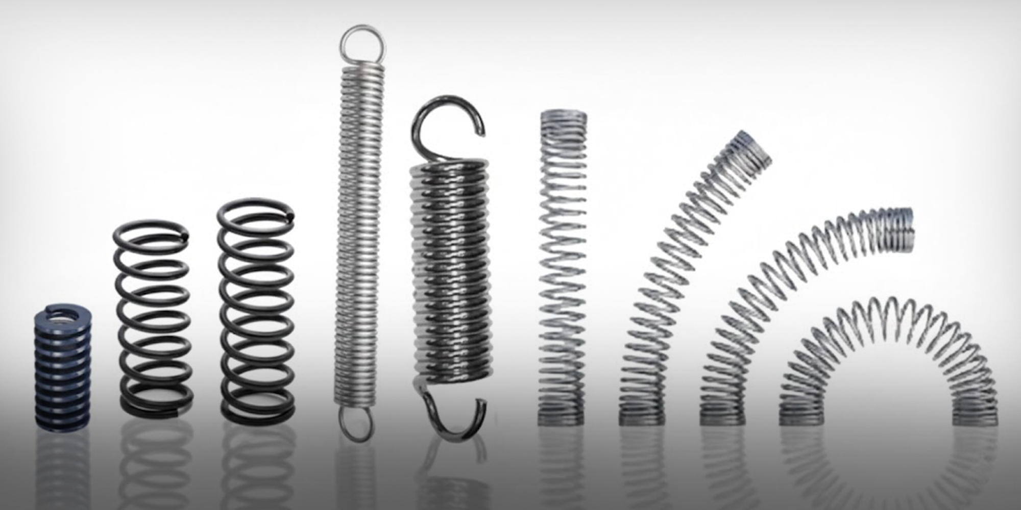
With the physics established, we now turn to the practical toolkit.
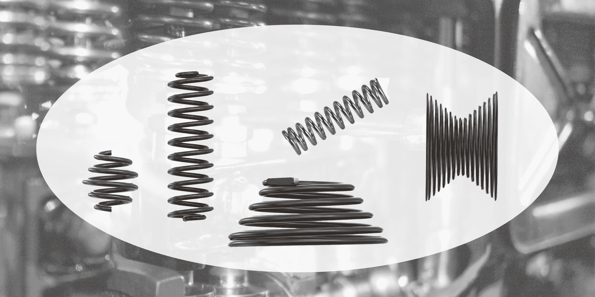
The following eight spring types form the core solutions for industrial design.
Understanding their distinct force profiles and optimal applications is the key to moving from concept to reliable operation.
When your application demands a near-constant force over a long stroke within a compact envelope, mechanical coil springs reach their limit.
Nitrogen gas springs are the engineered solution.

How They Work & Why They Excel:
Sealed within a precision cylinder and piston assembly is high-pressure nitrogen.
Unlike a coil spring whose force increases linearly (F=kx), a gas spring's force curve is far flatter, typically exhibiting less than a 10% force drop over its working stroke.
This is due to the gas compression law, where force rises gradually as volume decreases.
Key Engineering Advantages:
When axial space is the primary constraint, wave springs provide the optimal force-deflection solution where conventional round-wire springs cannot fit.

The Space-Saving Principle:
A wave spring is manufactured from flat wire, pre-formed into a coil with multiple waves per turn.
When compressed, these waves flatten, generating force.
This geometry allows it to be up to 50% shorter in free height and solid height than a round-wire spring of equivalent force and deflection.

Applications & Critical Design Note:
*Higher stress concentration at wave crests limits fatigue life
As the most versatile and widely used spring, the compression spring is the benchmark.
Performance is dictated by a specific mathematical balance:

Key Spec: Spring Rate (k)
The spring rate, defined as the force required per unit of deflection, reveals the true behavior of the component:
k = (Gd⁴)/(8nD³)
Where:
G ≈ 80,000 MPa (for carbon steel),
d= wire diameter,
n= active coils,
D= mean coil diameter


Why Wire Diameter Tolerance is Critical
Garter Springs – A Specialized Offshoot:
By joining the ends of a compression-style coil spring to form a continuous ring, you create a garter spring.

Its primary function is to exert a consistent, inward-directed radial force.
This makes it indispensable for sealing applications (lip seals, shaft seals), where it provides the uniform tension that maintains the seal's contact with a rotating or reciprocating shaft.
Torsion springs store and release energy by twisting about their central axis.
They are the go-to solution for returning components to a rest position (e.g., clip doors, counterbalanced lids) or providing a sustained rotational torque.

Critical Design Pitfall to Avoid:
As a torsion spring is wound (loaded), its body coil diameter decreases.
If designed around a mandrel, this causes binding—ask me how I know (spoiler: jammed door hinge on a production run).
Conversely, when unwound, the diameter increases and may jam in an outer housing.
Always specify and verify the mandrel/housing clearance in both the loaded and unloaded states.
A rotor spring (or power spring) is a highly specialized torsion spring designed for maximum energy storage in a minimal radial space.

It consists of a long, pre-stressed flat strip wound tightly onto an arbor. When released, it delivers a high initial torque that decays as it unwinds.
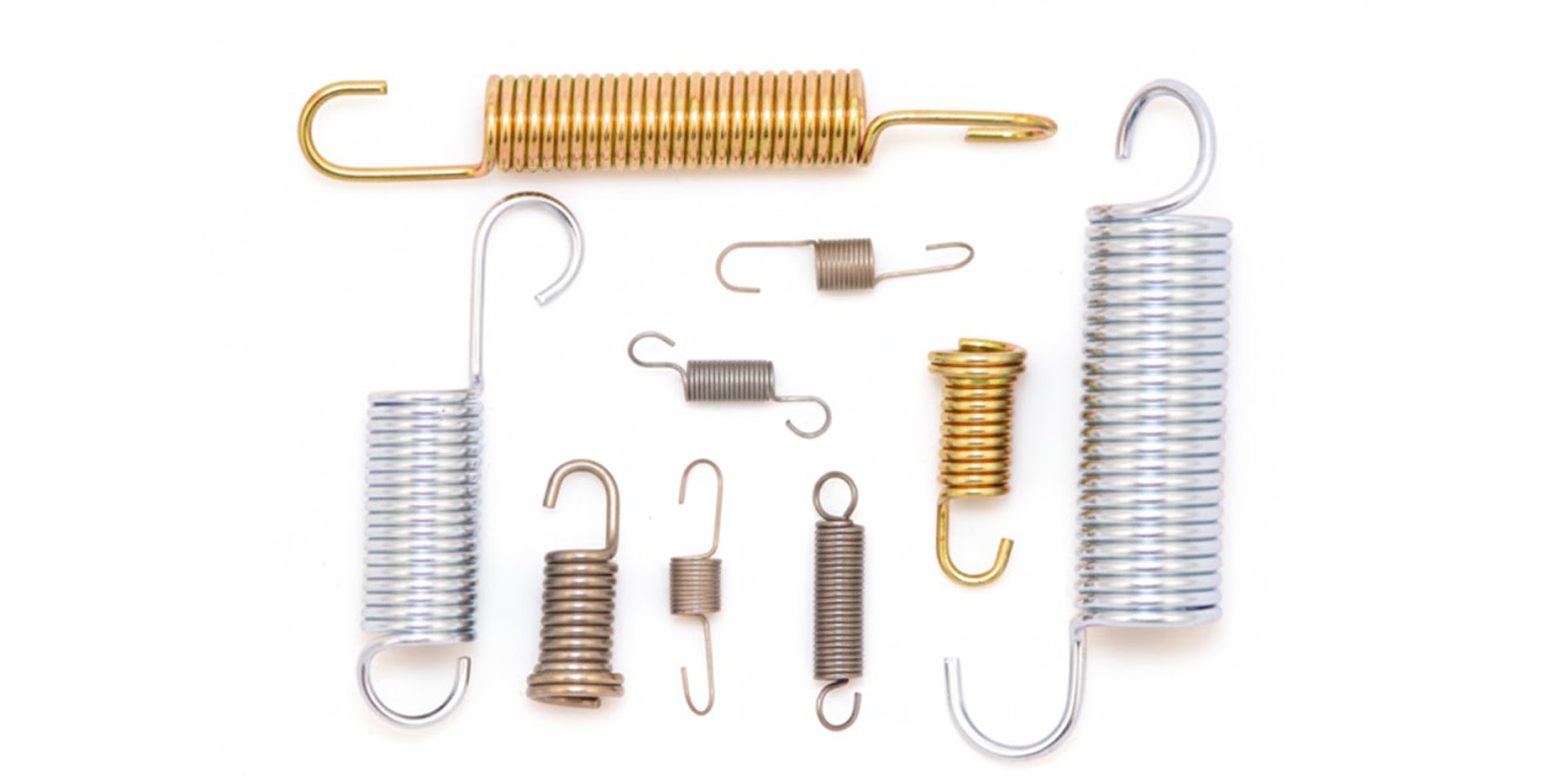
Extension springs are designed to resist a pulling force, with coils typically wound closed to provide initial tension.

The Two Pillars of Reliable Design:
Avoid sharp-bend German hooks for >10,000 cycles.
Specify full torsion loops or reduced-stress hooks (e.g., cross-over center hooks, side hooks) to distribute stress more evenly and dramatically extend fatigue life.
When you need immense force over a deflection measured in tenths of a millimeter, disc springs are the only solution.
These conical washers support loads orders of magnitude greater than coil springs of similar outer diameter.

Engineering Through Stacking:
Their genius lies in modular configurability. By stacking multiple discs:
Practical Example:
Need 10,000N load with 2mm deflection?
The formula:
Loadtotal = Loadsingle × nparallel
Deflectiontotal = Deflectionsingle × nseries
The stamping press environment is a torture test: impact loads, contamination, and cycles numbering in the hundreds of millions.
General-purpose compression springs will fail prematurely here.
The ISO 10243 Standard is Your Blueprint:
Die springs are classified by a universal color-coding system that defines their load capacity and ensures global interchangeability:

Critical Practice:
Always derate the static load rating for dynamic service.
A spring rated for 1000N static may only be suitable for 700N in a high-impact, high-cycle press application.
Material choice (typically chrome vanadium or silicon chromium) is optimized for shock resistance and fatigue life.
When helical springs fail to meet spatial or functional constraints, flat spring technology provides the answer.
By utilizing precision stamping and coining, we transform high-carbon steel and alloys (like 17-7 PH) into multi-functional mechanical components.

Starting from high-carbon spring steel or specialty alloys like 17-7 PH, our precision stamping, coining, and heat-treating processes produce functional components impossible to achieve through coiling.
Before you email that RFQ, answer these 5 questions:
1. What's my solid height vs. available space?
2. Static or dynamic load? (Cycles: ____)
3. Operating temperature: ____ °C
4. Environment: □ Indoor □ Outdoor □ Chemical exposure
5. Tolerance needed: □ Commercial (±15%) □ Precision (±5%)
Miss even one, and you'll get springs that "technically meet spec" but fail in service.
Use this checklist before finalizing any specification.
Define the installed height and fully compressed (solid) height.
The solid height is calculated as (Total Coils) * (Wire Diameter) for compression springs.
Always include a minimum “clash allowance” of 10-15% of the wire diameter to prevent coils from fully contacting, which causes stress to skyrocket and leads to immediate failure.
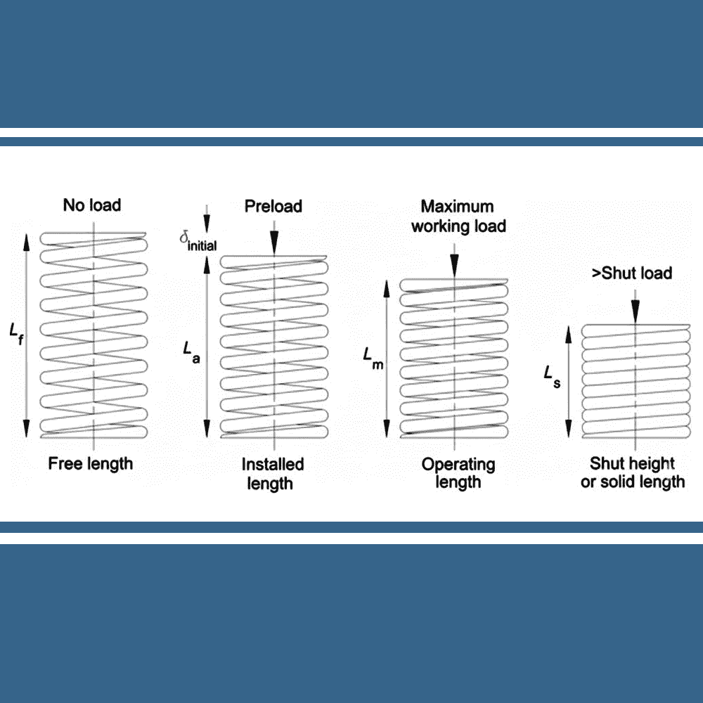
Key dimensional parameters defining the spring operating envelope
What is the required force at the installed height? At the operating height?
Is the application static (like a static preload) or dynamic (like a cycling mechanism)?
For dynamic applications: The consistency of the spring rate (k) is paramount. Specify tighter tolerance grades (e.g., ±10% instead of ±15% on k) to ensure repeatable machine timing and force output.
For springs designed for >10,000 cycles, you must perform a fatigue analysis.
The Modified Goodman Diagram is the standard engineering tool.
It plots the material’s alternating stress (from the cyclic load) against its mean stress (from the preload).
The goal is to keep the operating point well within the “infinite life” region (typically defined as 10^7 cycles for steel springs).
Factors like shot peening significantly expand this safe region.
Case Study: The 200K Cycle Surprise
Client spec'd a spring for "infinite life" at 50N mean load, 20N alternating.
Goodman chart showed we were safely in the green zone—until failures started at 200K cycles (target was 10M).
Root cause: They measured loads in a static test rig. Actual service had vibration-induced stress spikes hitting 90N peak.
The lesson? Always measure loads in the real operating environment, not on a bench.

As shown in the FEA stress analysis above, the peak stress (red zones) is concentrated on the inner diameter of the coils.
When vibration-induced spikes hit 90N, these localized stress points exceeded the fatigue limit, initiating micro-cracks that led to the 200K-cycle failure.
Never leave tolerances to chance. Reference published standards:
Selecting the right industrial spring is a systems engineering challenge.
It requires balancing spatial limits against force requirements, material cost against lifecycle performance, and theoretical models against manufacturing realities.
By applying the decision frameworks in this guide—from choosing a wave spring for space constraints to specifying 17-7 PH and shot peening for fatigue-critical roles—you move from guesswork to engineered reliability.
This directly translates to increased system MTBF, reduced unplanned downtime, and lower total cost of ownership.
Need a second opinion on your spring sizing?
The Lily Bearing engineering team provides complimentary load analysis—just send us your spatial envelope and force requirements. It’s faster and more reliable than trial-and-error prototyping.
All precision spring manufacturers recognize that spring performance is a critical concern. If a spring lacks reliability, the equipment it supports...
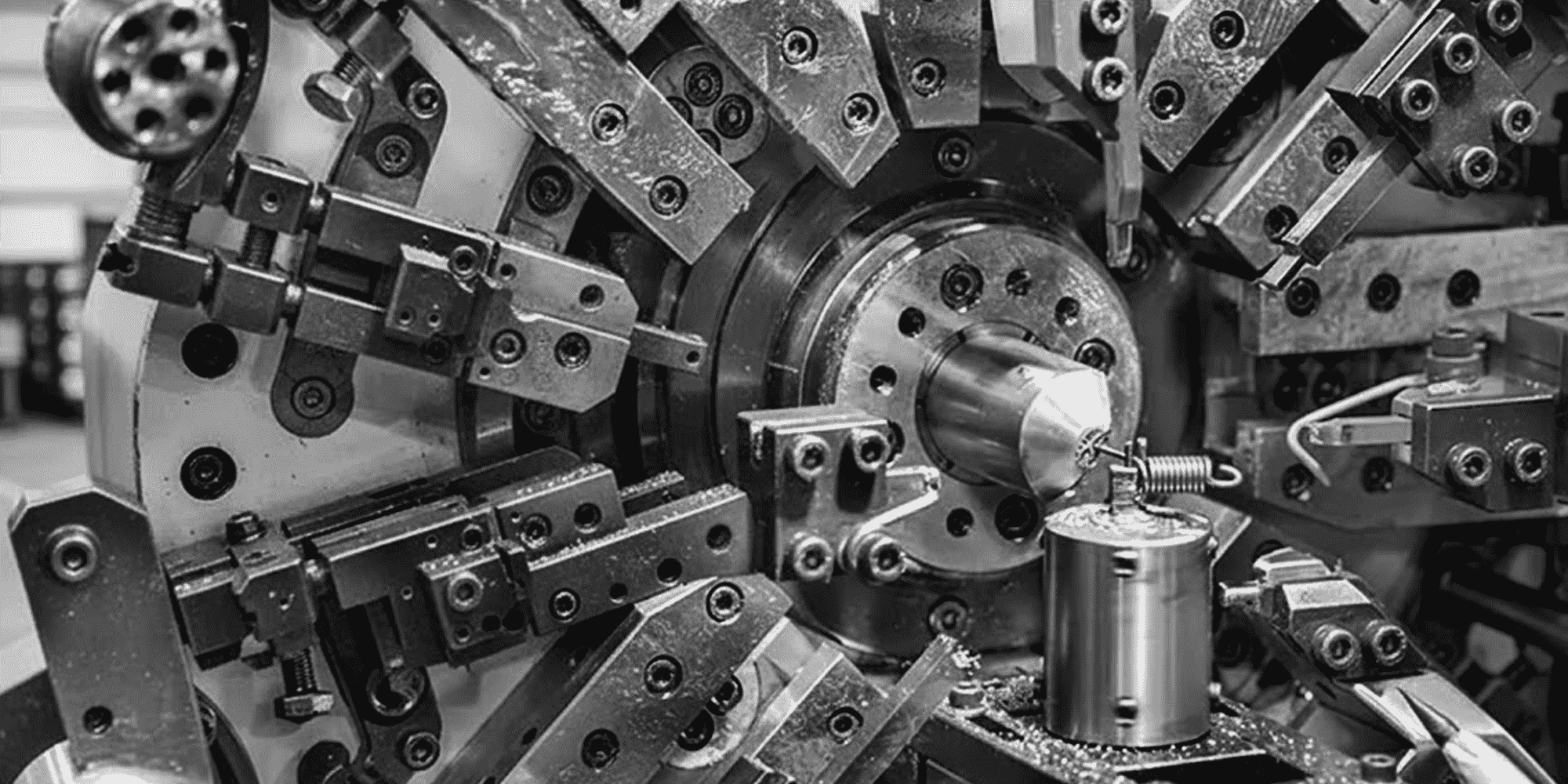
Turning a straight steel wire into a component that survives 10 million compression cycles isn't just a simple mechanical task. It takes precision...
When you think of a "spring," the image that likely comes to mind is a compression spring. As the most common type of metal spring, these devices are...