

 Richard
What Is a Compression Spring? Types, Design & Applications
A compression spring is an open-coil helical spring that resists compressive axial forces. When load is applied, it shortens and stores potential...
|
Every time a CNC router cuts a perfect slot, a 3D printer lays down a precise bead of filament, or a laser etches a microchip — a linear guide is making it possible. These unassuming components quietly underpin billions of dollars' worth of manufactured goods every year. |
|
±1 μm Typical positional accuracy of precision-class guides |
50,000+ Operating hours achievable with proper maintenance |
0.002 Typical coefficient of friction (vs. 0.1–0.3 for sliding guides) |
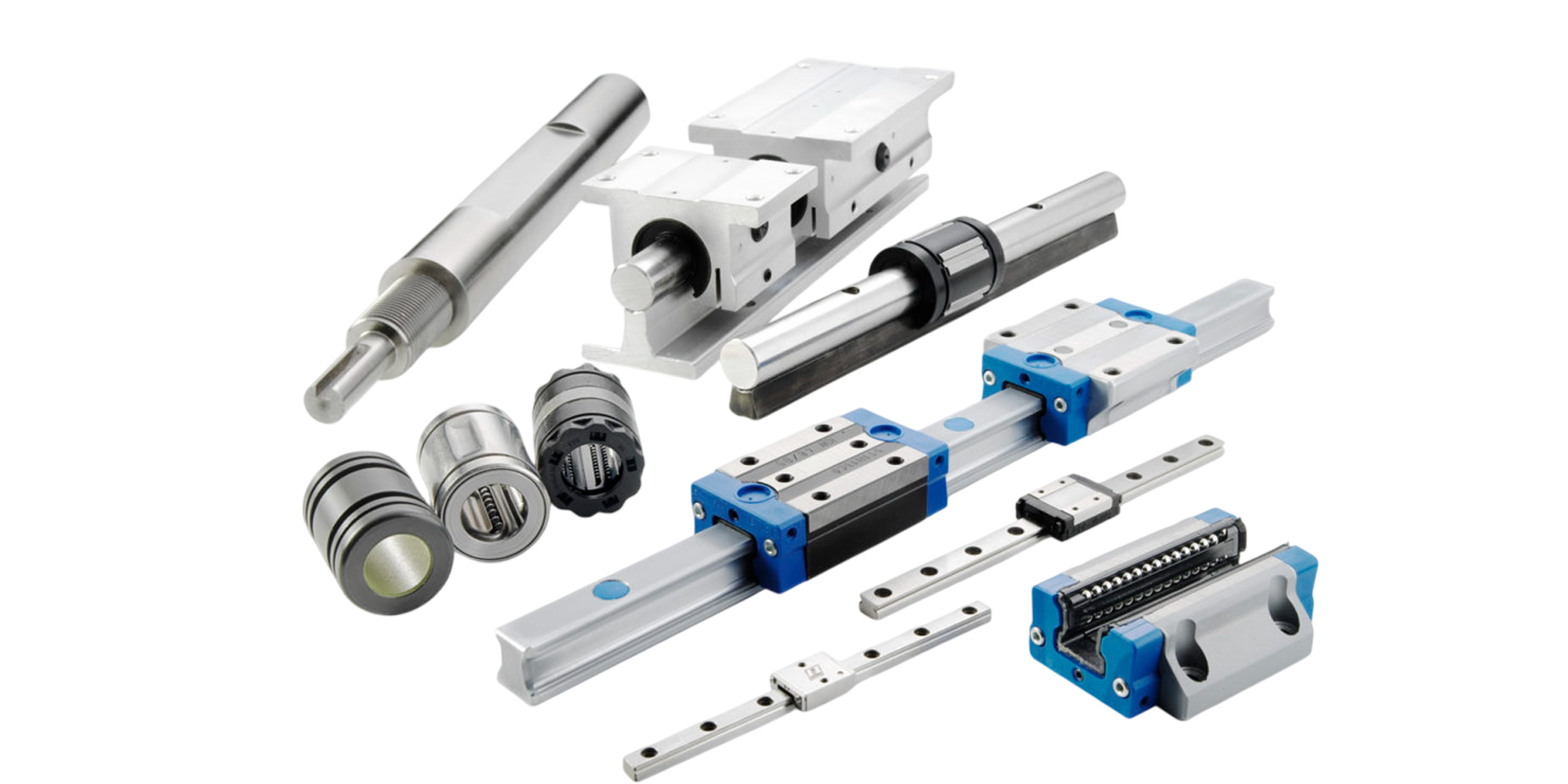
A linear guide (also called a linear rail, linear motion guide, or profiled rail guide) is a mechanical component that constrains motion to a single axis while bearing loads in all other directions.
In plain language: it lets something move in a perfectly straight line, smoothly and repeatedly, while holding everything else perfectly still.
Linear guides are found wherever controlled straight-line movement is needed — from the print head on your desktop printer to the gantry arm of a multi-ton industrial milling center. They are the workhorses of precision motion control.
|
Component |
Material |
Purpose |
|
Rail |
Carbon Steel / Stainless Steel |
Provides the precision track and mounting surface. |
|
Runner Block |
Alloy Steel / Aluminum |
Houses the bearings and attaches to the payload. |
|
Rolling Elements |
Chrome Steel / Ceramics / Silicon Nitride |
The "muscles" that carry the load. |
|
End Seals |
Synthetic Rubber / NBR |
Keeps dust out and lubrication in. |
|
Grease Nipple |
Brass / Steel |
The entry point for maintenance lubrication. |

The core operating principle of a modern profiled linear guide involves rolling contact between precision-hardened steel balls (or sometimes rollers) and a matched pair of raceways — one on the rail, one inside the carriage block. This rolling contact dramatically reduces friction compared to sliding surfaces.
Inside the carriage block, a chain of hardened steel balls circulates through a closed loop. The load-bearing balls travel along the precision-ground raceway on the rail, transmitting force.
When they reach the end of the load zone, they are swept into a return channel, travel back to the start, and rejoin the load zone — continuously and silently.
This recirculation means the carriage can travel any distance along the rail with the same number of load-bearing balls always in contact.
The contact angle — typically 45° in a Gothic-arch profile — allows the guide to carry loads in all four directions simultaneously: downward, upward, and both lateral directions.
|
PRO TIP — Contact Angle The 45° contact angle in Gothic-arch raceway profiles distributes load across four rows of balls. This gives profiled rail guides up to 10× the load capacity and 100× the rigidity of equivalent round-shaft guides — making them the standard choice for any serious precision application. |
Not all linear guides are created equal. The right type depends on your load, speed, precision requirements, and budget. Here are the four most common families:
|
Type |
Load Capacity |
Max Speed |
Accuracy |
Best For |
|
Profiled Rail (Ball) |
High (up to 100+ kN) |
Up to 4 m/s |
±1–5 μm |
CNC, automation, robotics |
|
Roller Guide |
Very High |
Up to 2 m/s |
±1–3 μm |
Heavy milling, grinding |
|
Round Shaft |
Low–Medium |
Up to 3 m/s |
±10–50 μm |
3D printers, light automation |
|
Miniature Rail |
Low |
Up to 2 m/s |
±1–3 μm |
Medical, optics, semicon |
|
Cross-Roller |
Medium |
Up to 1 m/s |
±0.5–2 μm |
Ultra-precision instruments |
|
⚠ SELECTION WARNING Never select a linear guide based on dynamic load rating alone. Moment loads (torques around pitch, yaw, and roll axes) are often the true limiting factor in carriage life, especially in cantilevered or offset-load applications. Always check the manufacturer's moment capacity table. |
Understanding the spec sheet is essential for making the right selection. Here is a breakdown of the most important parameters:
|
Specification |
What It Means |
Why It Matters |
|
Dynamic Load Rating (C) |
Load at which 90% of guides reach 50 km travel life |
Baseline for life calculations |
|
Static Load Rating (C₀) |
Max load before permanent deformation |
Critical for shock/impact loads |
|
Accuracy Grade |
H (Normal) → P → SP → UP (Ultra) |
Determines parallelism & height variance |
|
Preload Class |
Z0 (no preload) → Z3 (heavy) |
Higher preload = more rigidity, less play |
|
Rated Travel Life (L₁₀) |
Distance where 90% survive without fatigue |
Determines maintenance intervals |
|
Coefficient of Friction |
Typically 0.001–0.004 |
Drives motor sizing & heat generation |
|
“Precision is not a luxury in linear motion — it’s the product. A 5-micron error repeated across 10,000 machining cycles becomes a 50-millimeter dimensional drift. The guide is where tolerance is either built in or lost forever.” — Motion Engineering Principle |
Linear guides appear in a remarkable range of industries, often in places you would not expect:
The most demanding application. CNC machining centers use profiled rail guides on all three (or more) linear axes.
The requirement: sub-micron repeatability under loads of several kilonewtons, at traverse speeds up to 60 m/min, for millions of cycles. Only precision-class profiled rail guides with heavy preload meet this bar.
Wafer handlers, die bonders, and PCB pick-and-place machines push linear guides to their limits in the opposite direction — ultra-light loads but nanometer-level accuracy. This is the domain of miniature and cross-roller guides, often paired with air bearings at the extreme end of precision.
Surgical robots, CT scanner gantries, and lab automation equipment all require smooth, repeatable, whisper-quiet linear motion. Miniature profiled guides in stainless steel (for cleanability) are the standard solution here.
FDM 3D printers use round-shaft linear guides for the print head axes. Higher-end desktop CNC routers and laser cutters step up to miniature profiled rails. Even some premium camera sliders and film rigs use precision linear guides.
|
Industry |
Guide Type |
Key Requirement |
Example Machine |
|
CNC Machining |
HG/EG Profiled Rail |
Rigidity + load capacity |
5-axis milling center |
|
Semiconductor |
Miniature + Cross-Roller |
Nanometer precision |
Wafer stepper |
|
Robotics |
HG Profiled Rail |
Repeatability + speed |
SCARA linear axis |
|
Medical |
Miniature SS Rail |
Cleanability + smooth |
Surgical robot arm |
|
3D Printing / DIY |
Round Shaft / MGN |
Low cost + light load |
FDM printer |
|
Packaging |
HG or QH Rail |
Speed + cycle life |
Form-fill-seal machine |
Choosing the wrong guide is an expensive mistake. A systematic selection process follows these steps:
|
Step 1 |
Define Loads Calculate forces F, moment loads M, and apply a shock factor (1.5–3×) for dynamic conditions. |
|
Step 2 |
Speed & Stroke Determine maximum velocity, acceleration profile, and required stroke length. |
|
Step 3 |
Life Target Set the required L₁₀ travel life in km, or convert from operating hours × duty cycle. |
|
Step 4 |
Environment Assess dust, coolant, temperature extremes, and cleanliness requirements. |
|
Step 5 |
Size Selection Use the life equation: C ≥ F × (L/50)^(1/3) to find the minimum dynamic load rating. |
|
Step 6 |
Accuracy Grade Select H / P / SP / UP based on positional tolerance requirements. |
|
Step 7 |
Environment Assess dust, coolant, temperature extremes, and cleanliness requirements. |
|
✓ SELECTION RULE OF THUMB Apply a safety factor of 1.5–3× to your calculated dynamic load before selecting a guide size. For applications involving vibration, shock loads, or contaminated environments, use the higher end of this range. Under-specifying linear guides is one of the most common causes of premature failure in machine design. |
✓ Surface preparation is non-negotiable. The mounting surface must be flat to within the guide's accuracy grade tolerance — typically ±5–25 μm across the full rail length.
✓ Use a reference edge. Always install the rail against a precision-machined datum edge, not just bolted to a flat plate. The lateral reference is what gives you straightness.
✓ Torque bolts in sequence. Tighten from the center outward in a cross pattern, in at least two passes, to the manufacturer's specified torque. Over-tightening distorts the rail.
✓ Never hammer the carriage off the rail. Use the manufacturer's assembly jig or a smooth mandrel — or the balls will scatter.
✓ Initial lubrication is critical. Apply the specified grease before first operation. A dry start will score the raceways.
✓ Align parallel rails with a dial indicator. Parallelism must be within 20–50 μm or you'll dramatically reduce guide life.
|
Operating Condition |
Lubricant Type |
Interval |
Note |
|
Normal (clean, ambient) |
Lithium grease NLGI #2 |
Every 500 km / 3 months |
Use lube port or remove end cap |
|
High speed (>1 m/s) |
Low-viscosity oil (ISO VG 32–68) |
Continuous or every 50 km |
Oil mist or drip system recommended |
|
Contaminated / coolant |
Heavy grease + seals |
Every 100 km or monthly |
Install additional wipers/seals |
|
Clean room / medical |
PFPE grease (fluorinated) |
Per manufacturer schedule |
Avoid standard greases |
|
Food & beverage |
NSF H1 certified grease |
Every 200 km or monthly |
Stainless steel rail preferred |
|
⚠ MAINTENANCE WARNING Never mix different grease types. Incompatible base oils and thickeners can react and liquify, washing out of the carriage and leaving the raceways dry. When switching lubricant types, fully purge the old grease first. |
|
Increased Running Noise |
Clicking, grinding, or increased audible noise during traversal typically indicates ball damage, contamination, or insufficient lubrication. |
|
Positional Drift |
If a machine's dimensional accuracy degrades over time, worn raceways causing increased play are often the root cause. |
|
Elevated Carriage Temperature |
A hot carriage block after running suggests dry running, incorrect preload, or over-lubrication impeding ball circulation. |
"Linear bearing" is a broad term that includes any bearing supporting linear motion — including plain bushings, round-shaft ball bushings, and profiled rail systems. A "linear guide" most commonly refers specifically to a profiled rail guide system. All linear guides include linear bearings, but not all linear bearings are linear guides.
With correct selection, proper installation, and regular lubrication, profiled linear guides routinely achieve 10,000–50,000+ hours of service life, or hundreds of thousands of kilometers of travel. In practice, contamination and dry running kill guides far sooner than mechanical fatigue.
Yes. Profiled linear guides support loads in all four perpendicular directions, so vertical orientation presents no technical challenge. However, lubricant may drain faster — check the manufacturer's lube interval recommendations for vertical mounting.
Preload is a slight interference fit between the balls and raceways, applied by using slightly oversized balls. It eliminates all clearance (play), dramatically increasing rigidity and accuracy. The trade-off: higher preload increases friction and reduces rated travel life.
All three are world-class manufacturers. THK invented the profiled linear guide and sets the benchmark for ultra-precision grades. HIWIN offers excellent quality-to-cost ratio and dominates cost-sensitive CNC and automation. Bosch Rexroth excels in European industrial automation with excellent global service networks.
Linear guides convert any actuator — motor, cylinder, or human hand — into controlled, repeatable straight-line movement.
The profiled rail system, with its recirculating Gothic-arch raceways, has become the universal standard because it uniquely combines high load capacity, ultra-low friction, four-direction support, and long service life in a compact, bolt-on form factor.
Whether you're sizing a CNC axis, specifying a robotic joint, or building a precision instrument, understanding linear guides is one of the most high-value skills in mechanical engineering.
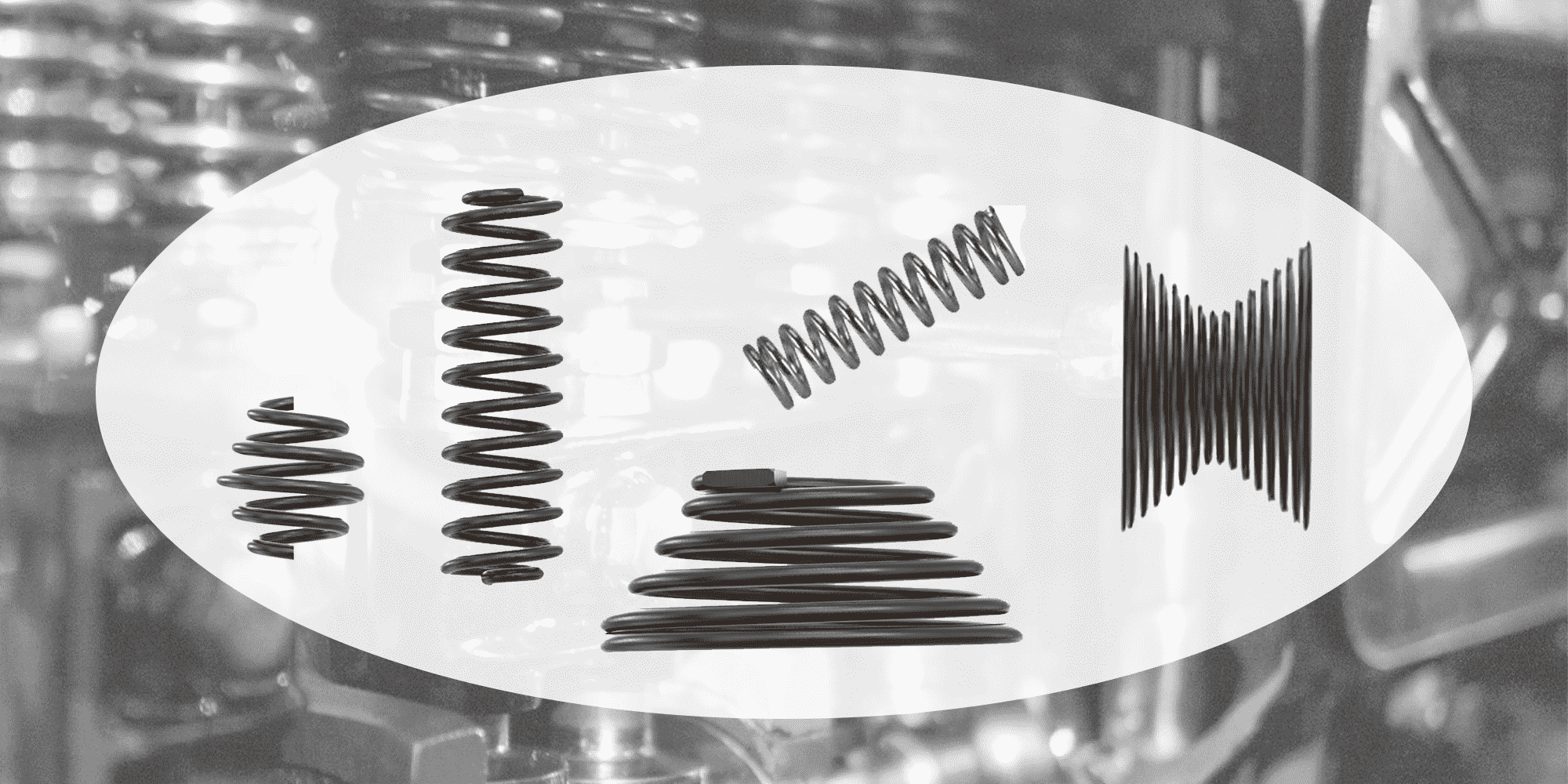
A compression spring is an open-coil helical spring that resists compressive axial forces. When load is applied, it shortens and stores potential...
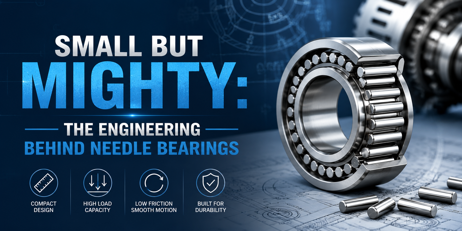
What Are Needle Bearings? Needle bearings are a specialized type of roller bearing that use long, thin cylindrical rollers — called needles — to...
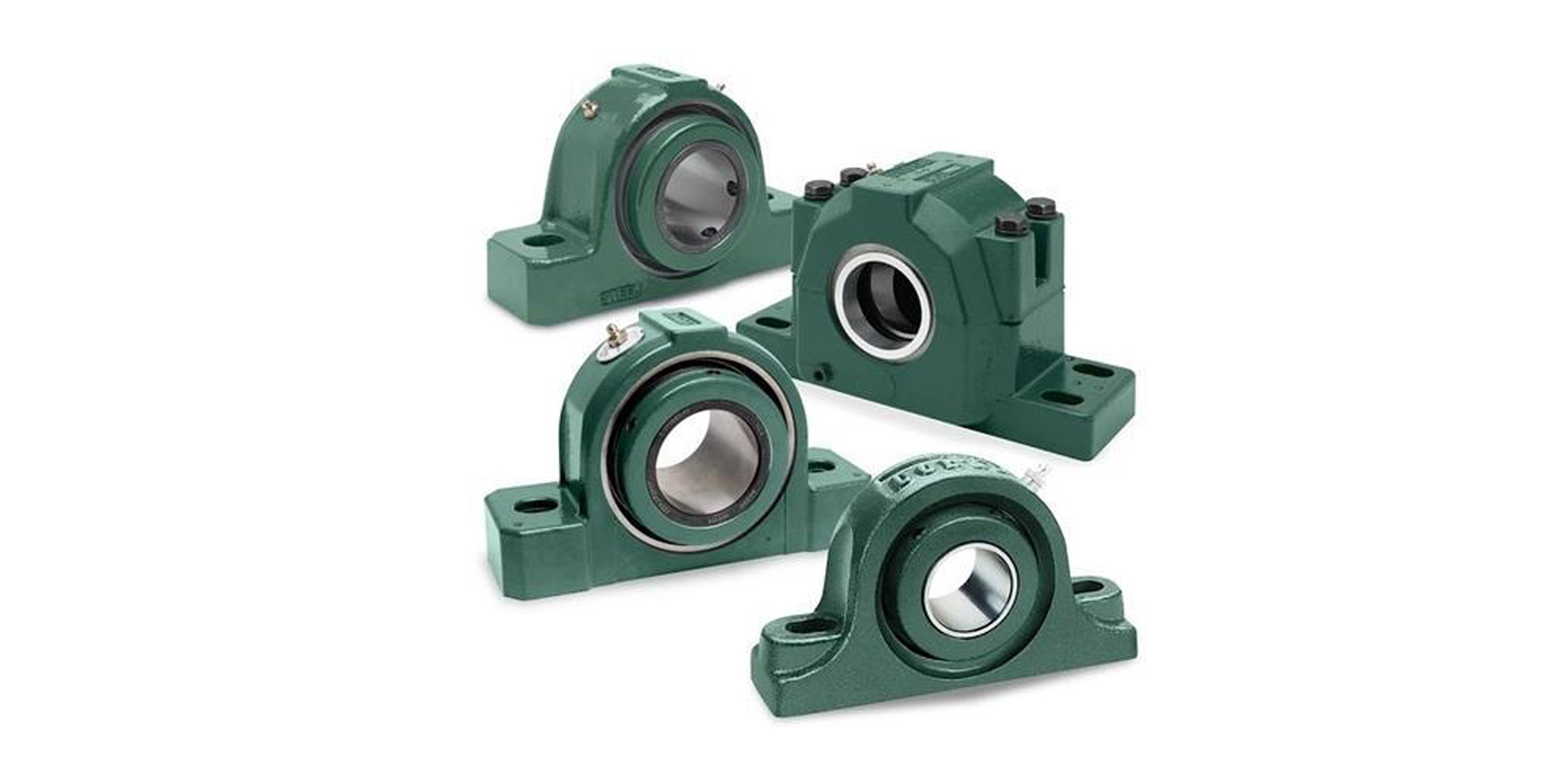
Pillow block bearings are among the most widely deployed mounted bearing solutions in industrial machinery. Understanding their load capacity — from...