

 William
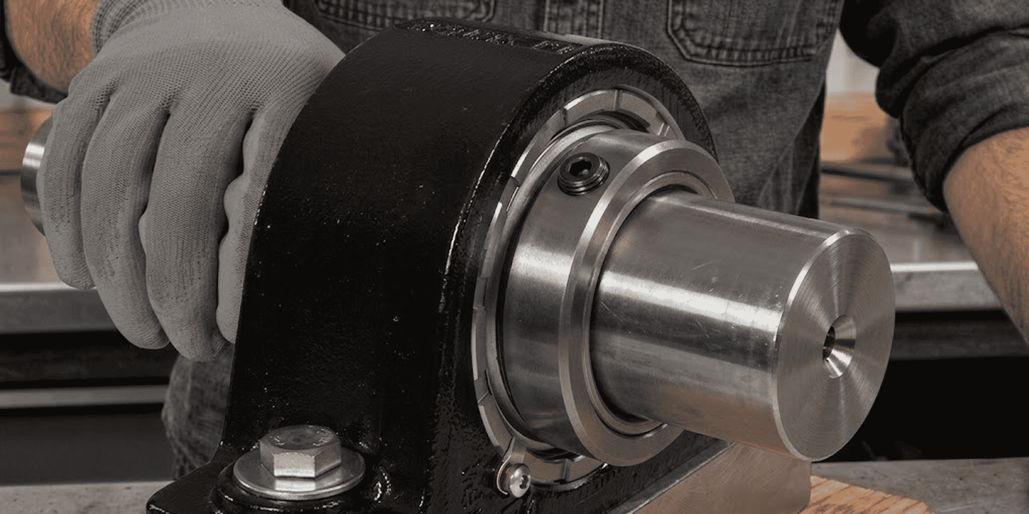
How to Install Pillow Block Bearings: Step-by-Step Guide
Quick Answer — 8 Steps Clean and inspect the shaft Slide the bearing into position Lightly bolt the housing down Set the final mounting...
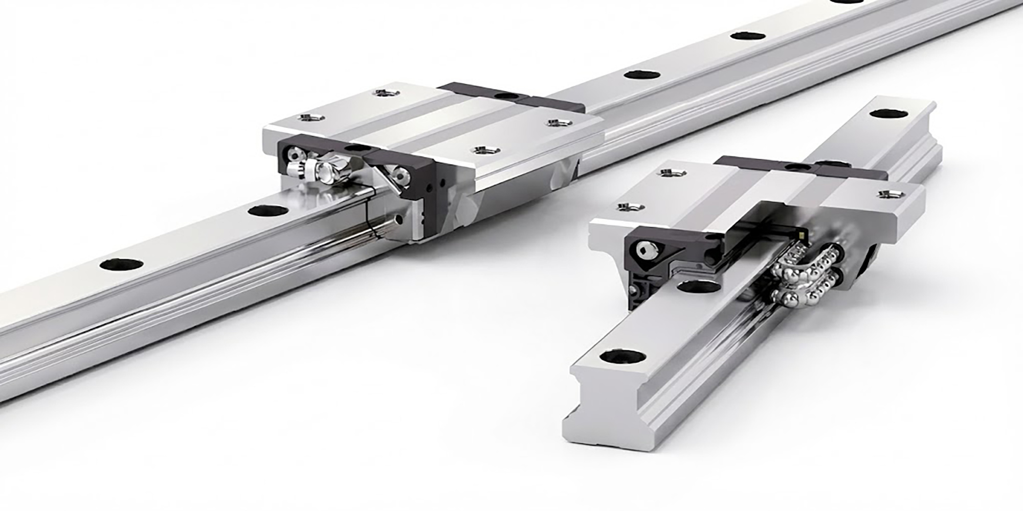
Linear rail guides are engineered for applications requiring precise motion and strong load capacity. However, incorrect installation can introduce unwanted stresses, shorten service life, and compromise the system’s built-in travel accuracy.
By understanding and following the mounting guidelines, you can ensure your linear guide system performs with the expected precision. This also helps prevent premature failure.
Linear guideways provide the same load capacity in radial, reverse-radial, and lateral directions. Their use depends on the machine’s requirements and the direction of applied loads. Common configurations for linear guideways are illustrated below.


Rails and blocks may shift when the machine experiences vibrations or impacts. To prevent this and ensure high operational accuracy, it is recommended to use the following four fixing methods.


Before installing linear guides for the first time, it is advisable to perform a trial installation to become familiar with the process.
During this trial, precisely measure the accuracy of the machine’s mounting surfaces and the linear guides. This helps you understand how they relate to the required table accuracy.
This helps determine the required precision of the machine base and the appropriate accuracy grade of the linear guides. It also clarifies the extent and method of accuracy measurements needed.
Following these steps ensures that no issues occur when the machine enters full-scale production.
When installing linear guides for the first time, be sure to follow the procedures in this manual closely.
Check whether the mounting surface meets the flatness and straightness requirements for the linear guide. Typically, the flatness and straightness should be within 0.02 mm. However, the exact tolerance may vary depending on the specific model and type of linear guide used.
Before installing the LM Guide, make sure to clean the machine’s mounting surface, removing any burrs, dents, or dust.
Since the LM Guide comes coated with anti-rust oil, wipe the reference surface with cleaning oil to remove it before use. After the anti-rust oil is removed, the reference surface can easily rust. To protect it, apply a light, low-viscosity spindle oil.

Position the linear guide on the base and temporarily secure it with the drive screw or other fixtures. Make sure it aligns correctly with the datum line.
Before fully tightening, check the alignment of the screw holes. Applying excessive tightening force can misalign the holes. This misalignment may cause offsets that compromise accuracy and overall quality.

Tighten the set screws of the LM rail in sequence. Apply just enough force to ensure the rail is firmly in contact with the side mounting surface.

Use a torque wrench to tighten the bolts, working from the center outward toward both ends.

Repeat the same steps to install the auxiliary rail, then mount the blocks onto the rail individually. Make sure to install all accessories—such as lubrication fittings, grease fittings, and seals—at this stage. If you wait until later, the limited space may make installing these components difficult.

Position the table gently onto the carriages on both the main and auxiliary rails.

Tighten the perpendicular thrust screw to properly seat the table, then fasten the table’s mounting screws in the specified order.

After installing the guideways in the machine, lubricate the blocks using a lithium soap-based grease or oil.
The guideways are delivered coated with anti-corrosion oil. If the rails were cleaned prior to installation, ensure they are properly lubricated after assembly. Confirm that the lubricant is compatible with the anti-rust coating on the rails.
Since the blocks contain various plastic components, avoid prolonged contact with organic solvents during cleaning. This prevents potential damage.
Prevent foreign objects from entering the blocks, as this can harm the guideways.
Do not disassemble the blocks, as careless disassembly may allow debris to enter and reduce precision or cause damage.
When handling the guideways, always keep them horizontal to prevent the blocks from falling off the rails.
Avoid dropping or striking the blocks, as impacts can impair the functionality of the guideways.
The most common setup for linear rail guides uses two rails and four carriages. However, no matter how many carriages are used, installing two rails in parallel can introduce unwanted side loads. This occurs if they are not aligned within the manufacturer’s parallelism tolerance.
There are several ways to secure the rails and maintain straightness. The most accurate method uses a precisely machined reference edge for each rail. More economical approaches include aligning one rail with a straightedge or gauge. The second rail can then “float” into alignment using a connecting plate.
Keep in mind that if the rails are not positioned against a reference edge or retaining strip, the allowable side load may decrease. Without lateral support, the shear strength of the mounting screws becomes the limiting factor for how much side force the system can withstand.
When two rails operate in parallel, they must also meet the allowable vertical offset limit. This value depends on the spacing between the rails and the preload of the carriages. Higher preload levels mean the system can tolerate less vertical offset. Exceeding this limit introduces a rolling moment on the carriages, which can significantly reduce bearing life.
When determining the vertical offset, you must include the carriage height tolerance, H. If adding the height tolerance creates an offset greater than the allowable limit, choose carriages with lower preload. Alternatively, opt for higher-precision carriages.
When several carriages are installed on the same rail, the vertical offset between them is a key consideration. This offset can create a pitch moment on the carriages. The allowable vertical offset depends on both the carriage length (standard, short, or long) and the spacing between the carriages.
As with rail-to-rail offset, the calculation must include the height variation between carriages. If the actual vertical offset exceeds the permissible value, then shorter carriages or higher-precision carriages should be selected.
Naturally, correct installation involves more than just component-related factors. Base conditions, reference-edge geometry, and even the screw-tightening sequence all influence performance.
In less demanding applications, simpler installation methods may still work adequately. For high-precision systems, strictly follow the manufacturer’s mounting and installation guidelines. This ensures maximum accuracy and prevents premature wear.
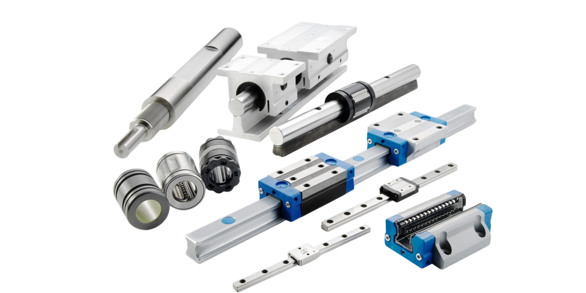
Installing linear guides correctly is critical for achieving precise, reliable, and long-lasting motion in any machine. By adhering to these best practices, you ensure optimal alignment and smoother travel. This also helps achieve the longest possible service life for your linear motion system. Explore the full range of linear guides at lily bearing.
Quick Answer — 8 Steps Clean and inspect the shaft Slide the bearing into position Lightly bolt the housing down Set the final mounting...
Every time a CNC router cuts a perfect slot, a 3D printer lays down a precise bead of filament, or a laser etches a microchip — a linear guide...
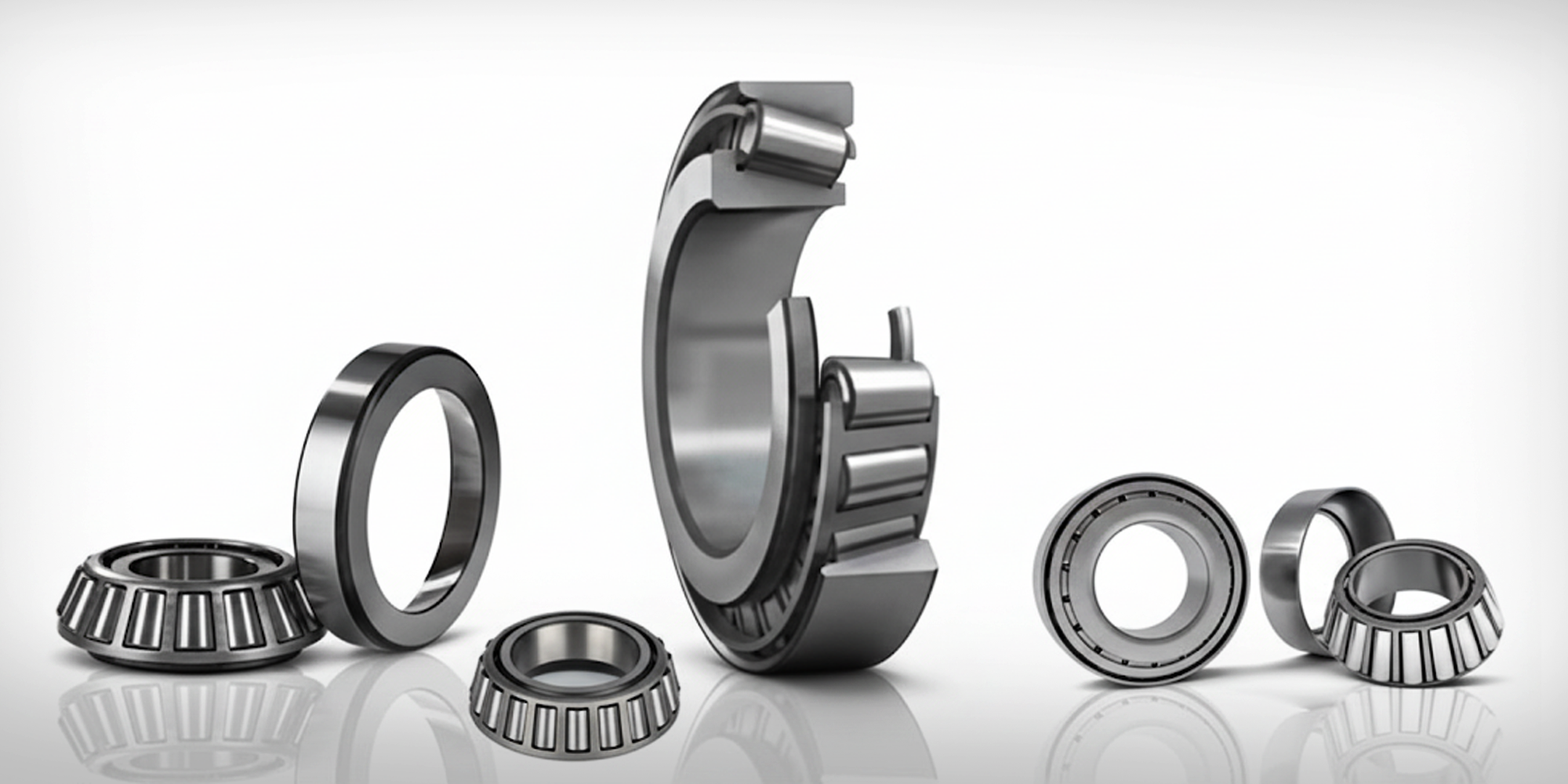
What Is the L44643 Bearing? The L44643 is a single-row tapered roller bearing cup (cone) that belongs to the inch-series bearing family, governed...