

 William
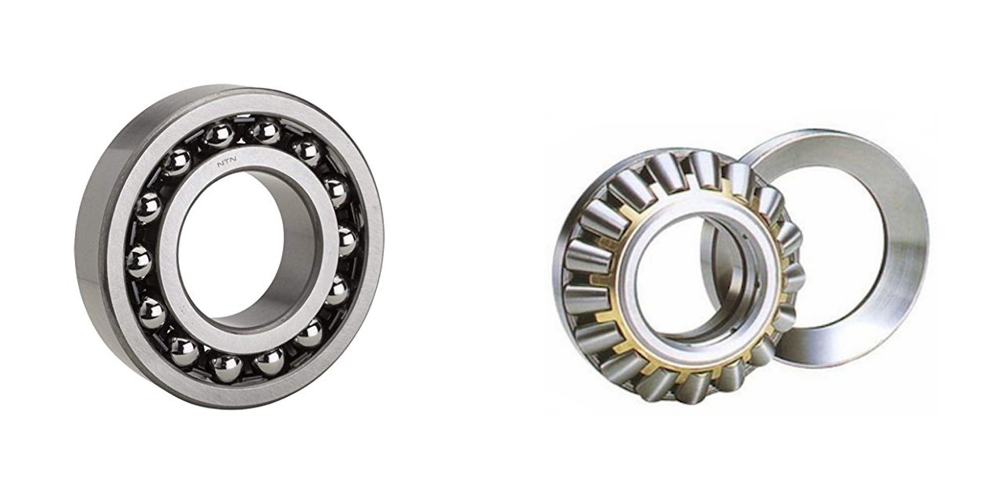
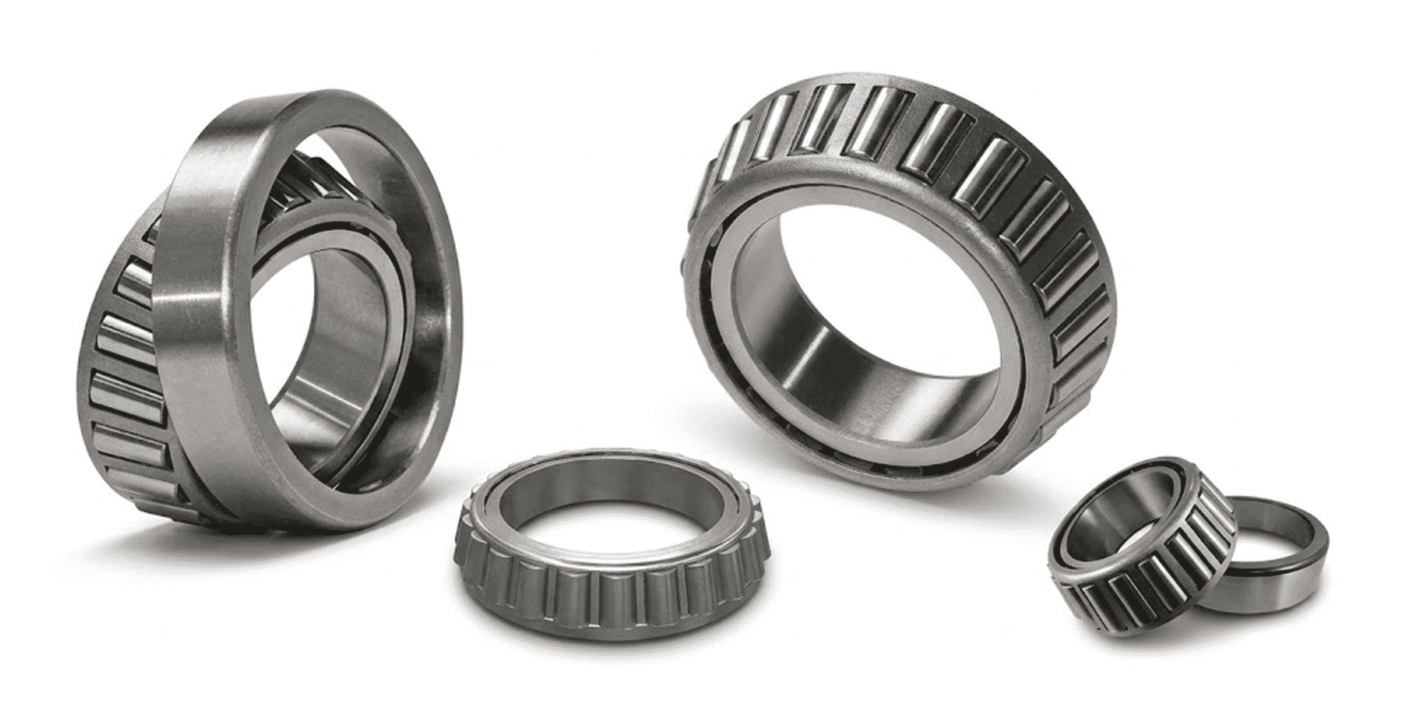
Ball Bearings vs. Roller Bearings
Bearings are essential parts of machines and equipment. They reduce friction, making it easier for parts to move smoothly. Two main types of bearings
Walk the floor of any large crane manufacturer or wind turbine assembly plant and you'll find one component that makes everything else possible — the slewing bearing.
Strip it out and you've got a machine that can't rotate. Keep it running well and you've got equipment that works smoothly for decades.
The global slewing bearing market was valued at approximately $4.8 billion in 2023 and is projected to reach $7.2 billion by 2033 at a CAGR of 5.3% — a trajectory driven by surging demand in construction, renewable energy, and industrial automation.
Over 78,000 large construction cranes worldwide currently rely on slewing ring technology for their 360° rotation capability.
This guide covers exactly what a slewing bearing is, how it works, what the different types do, and where each one is used — with enough technical detail to actually help you make decisions.
A slewing bearing — also called a slewing ring, slew ring, slew bearing, or turntable bearing — is a large-diameter rotational bearing designed to simultaneously support axial loads, radial loads, and moment (tilting) loads.
Unlike standard bearings that handle primarily one load direction, a slewing bearing handles all three at once, which is what makes it indispensable in heavy rotating equipment.
Slewing bearings are manufactured in diameters ranging from 200 mm to over 6,000 mm, with some specialty applications pushing beyond 8 meters.
They typically feature two concentric rings (inner and outer), rolling elements between them, and — in many designs — integrated gear teeth on one ring for driven rotation.
The result is a single compact unit that replaces what would otherwise require multiple separate components: a bearing, a gear ring, and a support structure.
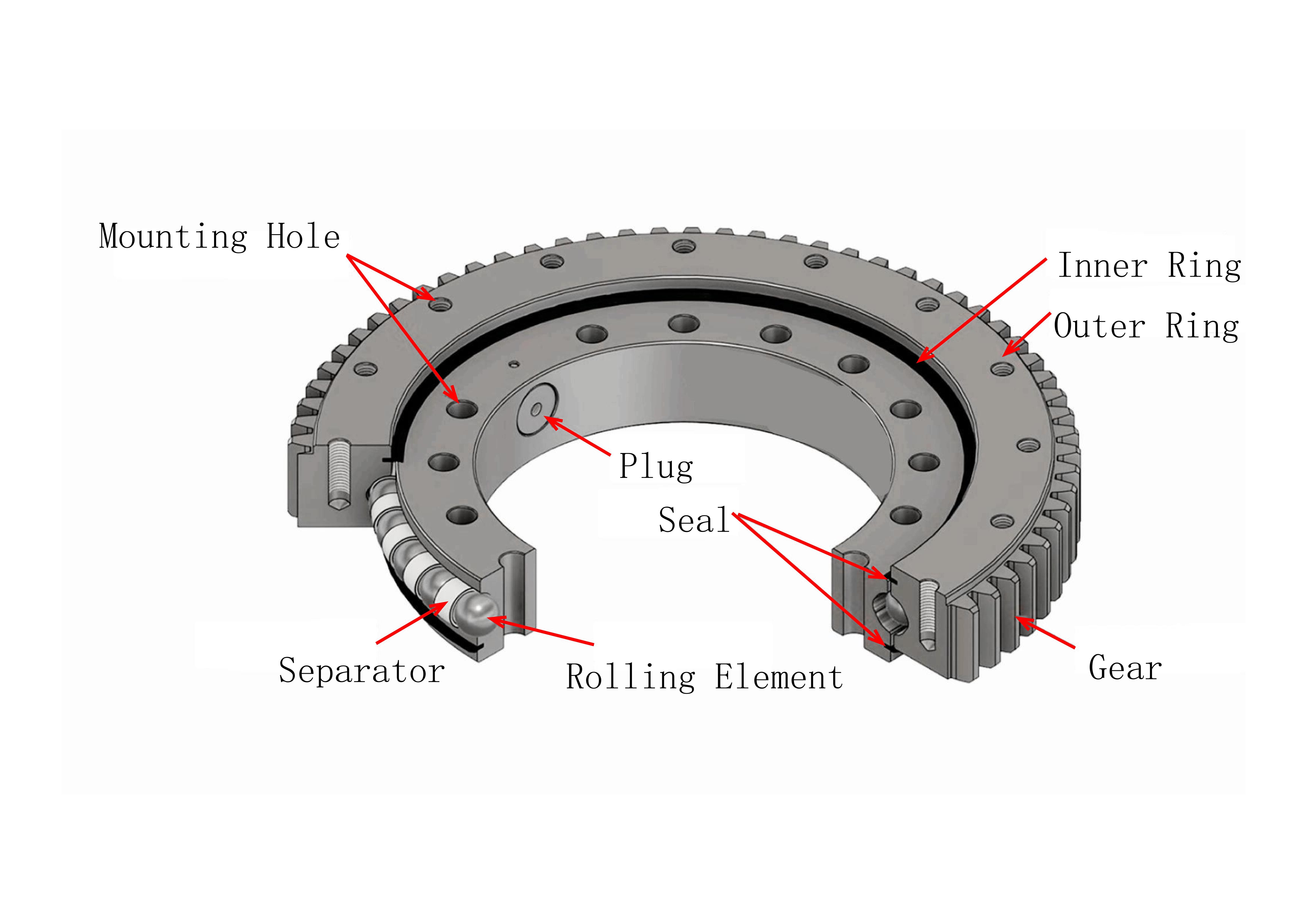
Fig 1 — Structure of a Slewing Bearing
At a Glance
|
200 mm – 6,000+ mm Typical diameter range |
3 Load Types Axial, radial & moment — simultaneously |
|
360° Full rotational capability |
9M+ units/yr Deployed globally in industrial machinery |
Understanding the components of a slewing bearing makes it easier to evaluate specifications, diagnose wear, and select the right type for an application. Here's what each part does.
Three mechanical principles govern slewing bearing operation: rotation through rolling elements, simultaneous multi-axis load distribution, and — in geared variants — powered torque transmission.
When one ring turns relative to the other, the rolling elements roll along the raceways rather than slide — this is the essential distinction between a bearing and a plain bushing.
Rolling contact reduces the friction coefficient to approximately 0.006 (compared to 0.1–0.3 for sliding contact), which is why a single operator can rotate a multi-tonne crane superstructure with a modest electric motor.
The rolling elements are confined to the raceway geometry, so the inner ring stays precisely centered on the outer ring throughout the full 360° of rotation.
This concentricity is what gives slewing bearings their positional accuracy — critical in applications like CT scanner gantries or radar antenna pedestals where geometric accuracy directly affects performance.
A slewing bearing handles three fundamentally different load types at the same time:
Axial Load (Thrust Load)
Force acting parallel to the bearing's rotation axis — essentially the weight of everything sitting on top of the bearing, plus dynamic vertical forces. In a tower crane, this is primarily the weight of the jib, counterweight, and hoisted load transferred downward through the slewing ring.
Radial Load
Force acting perpendicular to the rotation axis — horizontal forces such as wind loading on a crane jib or the lateral component of a bucket crowd force on an excavator. Radial loads are distributed across the rolling elements' contact zones along the outer circumference of the bearing.
Moment Load (Tilting Moment)
A rotational force that tries to tilt one ring relative to the other — generated whenever a load is applied at a distance from the bearing's center. A crane with a 10-tonne load at 20-meter radius creates a tilting moment of 200 tonne-meters. This is typically the governing load case in slewing bearing selection and the reason bearing diameter matters as much as rated capacity.
These three loads act simultaneously and their combined effect is distributed across all the rolling elements in contact with the loaded raceway.
The bearing's rated capacity figures — always quoted separately for axial, radial, and moment loads — define the envelope within which the bearing can operate safely for its design life.
Geared slewing bearings incorporate machined gear teeth directly on one ring, creating an integrated drive interface. An electric motor drives a small pinion that meshes with the gear ring, producing controlled rotation. The gear ratio between pinion and ring gear determines the torque multiplication and speed reduction — a common arrangement in construction cranes uses gear ratios that reduce motor speed by a factor of 50:1 or more, generating the high output torque needed to swing a loaded jib.
Each slewing bearing type has a specific load profile it handles best. Selecting the wrong type doesn't just reduce performance — it can lead to premature failure. Here's what distinguishes each design.
Quick Comparison
| Type | Load Capacity | Rigidity | Best For |
|---|---|---|---|
| 4-Point Ball | Medium | Medium | Multi-directional loads |
| 8-Point Ball | Medium-High | High | Complex loading, dual row |
| Cross Roller | High | Very High | Precision, compact space |
| 3-Row Cross Roller | Very High | Very High | Heavy-duty, separated loads |
| Ball + Roller Combined | High | High | Mixed load environments |
In a four-point contact ball bearing, each ball contacts the raceway at four distinct points — two on the inner ring, two on the outer.
This geometry is achieved through a Gothic arch (or "double-V") raceway profile.
The four-contact arrangement allows a single row of balls to handle axial loads in both directions, radial loads, and moment loads simultaneously.
This versatility makes the four-point design the most widely used slewing bearing type.
It's found in mobile cranes, aerial work platforms, and packaging machinery — anywhere a compact, multi-directional solution is needed.
The trade-off: under heavy pure moment loading, the contact angle shifts and stress concentrations increase.
For applications with extreme tilting moments, a cross-roller or three-row design is typically more appropriate.
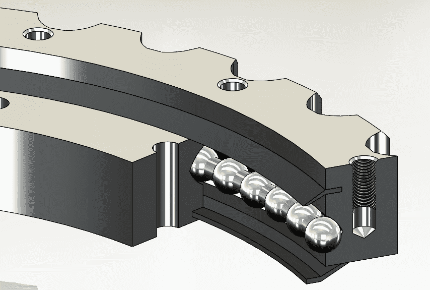
Fig 2 — Four Point Contact Ball Bearing
The eight-point contact design uses two rows of balls, each row having four contact points — giving eight total contact zones between balls and raceways.
This doubles the load-sharing capacity compared to a single-row four-point design.
The dual-row arrangement also increases moment capacity significantly: with more contact points distributed across a wider axial span, the bearing resists tilting more effectively.
This type suits applications with complex, variable loading — such as tunnel boring machine cutterhead supports or offshore pedestal cranes — where load direction changes frequently and load magnitude is high.
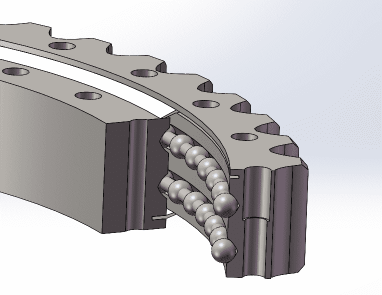
Fig 3 — Eight Point Contact Ball Slewing Ring
Cross roller slewing bearings arrange cylindrical rollers in an alternating 90° pattern — one roller with its axis horizontal, the next vertical, and so on around the circumference.
This alternating arrangement means each roller can support loads from a different direction, giving the bearing the ability to simultaneously handle axial, radial, and moment loads without geometric compromise.
Line contact between rollers and raceways produces significantly higher load capacity per element than point contact in ball bearings.
Rigidity is also higher — the cross arrangement resists deflection better than ball designs, which is critical in precision applications.
Cross roller slewing bearings are the preferred choice for robotic joint assemblies, medical imaging equipment, and radar pedestals — any application that demands both high load capacity and tight geometric accuracy in a compact diameter.
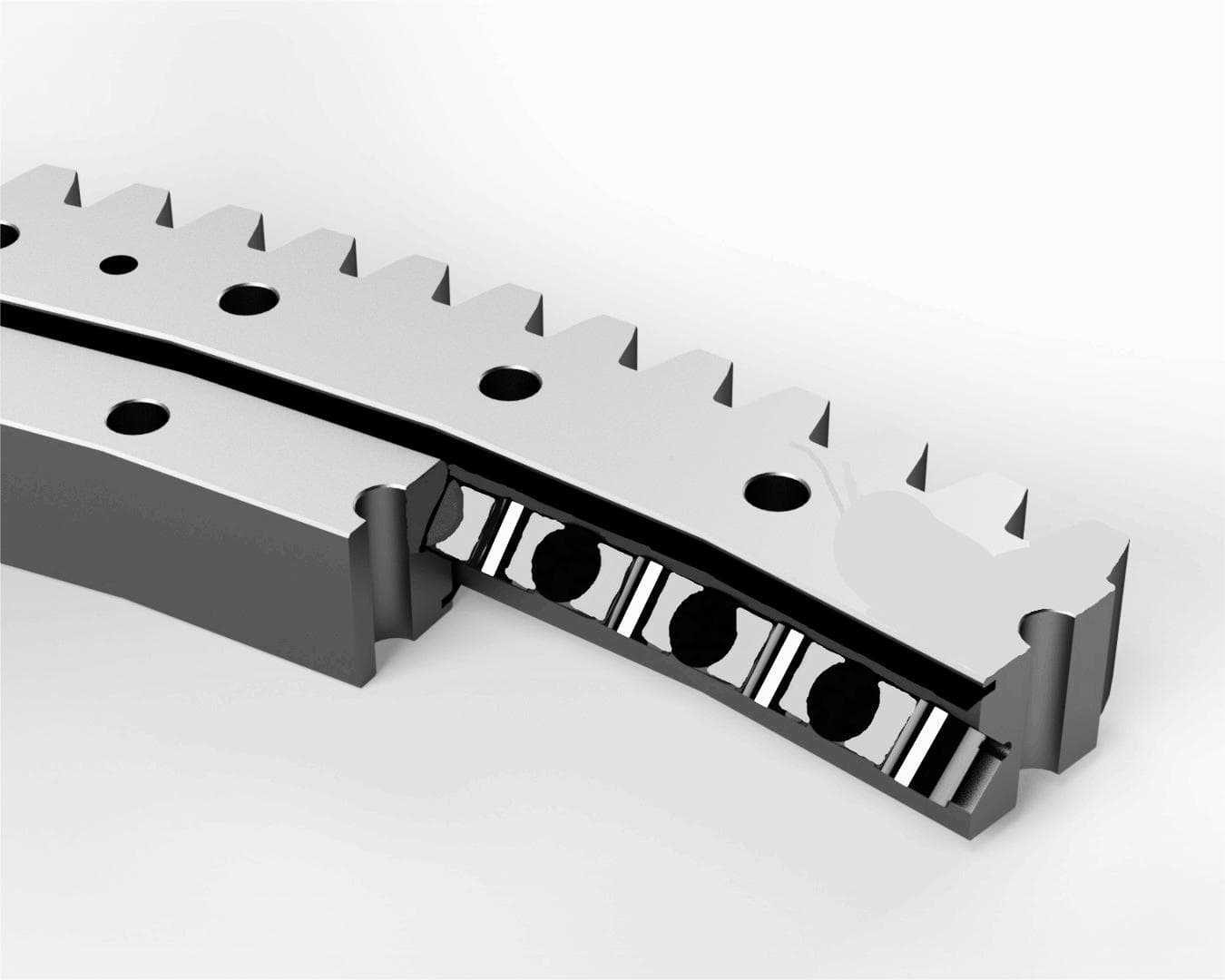
Fig 4 — Cross Roller Slewing Ring
Where a standard cross roller bearing uses one row of alternating rollers for all load types, the three-row design separates the function: one row of rollers handles axial load in one direction, a second row handles axial load in the other direction, and a third row handles radial load.
Each row has its own dedicated raceway.
This separation of function means each row is optimized for its specific load rather than compromised by multi-directional demands.
The result is a bearing with substantially higher overall load capacity than an equivalent-diameter single-row design — at the cost of greater axial height and weight.
Three-row cross roller bearings are typically specified for the heaviest applications: large port cranes handling 100+ tonne loads, steel mill equipment, and large tunnel boring machines.
Operators now expect these bearings to withstand more than 25,000 hours of continuous operation under high loads.
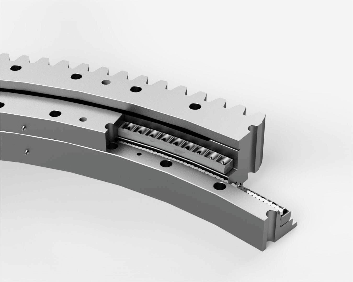
Fig 5 — Three-Row Cross Roller Slewing Ring Bearing
Combined bearings use balls in one row and rollers in another, each row optimized for a specific load type.
The ball row typically handles axial loads and moment loads, while the roller row manages radial loads.
This division allows the designer to tune each row independently — using a ball geometry that minimizes contact stress under tilting and a roller geometry that maximizes radial stiffness.
Combined bearings are common in agricultural machinery, forestry equipment, and material handling applications where load profiles shift significantly between operating modes.
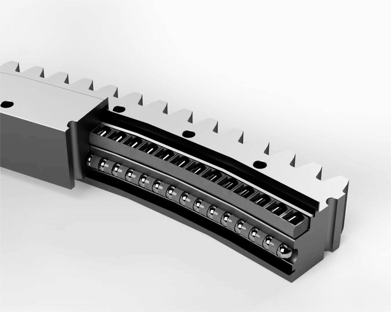
Fig 6 — Combined Bearings (Ball and Roller)
Over 85% of large-diameter bearing installations in cranes, wind turbines, and tunnel boring machines rely on slewing bearings.
The wind energy segment alone accounts for approximately 45% of global slewing bearing demand, with nacelle-mounted bearing installations exceeding 35,000 units in 2023.
Here's how different industries use them — and what each application demands from the bearing.
Construction: Cranes & Excavators
Tower cranes, mobile cranes, and truck cranes all use slewing bearings at the junction between the stationary mast or chassis and the rotating superstructure.
The bearing must support the full weight of the upper structure plus the hoisted load — which on a large tower crane can exceed 100 tonnes — while enabling continuous 360° rotation under wind loading.
Excavators use slewing bearings at the house-to-undercarriage connection, allowing the entire upper structure to swing independently of the tracks. A typical 50-tonne excavator generates tilting moments at the slewing bearing that exceed 500 kNm during heavy digging cycles.
Wind Energy: Turbine Yaw & Pitch Systems
Modern wind turbines use slewing bearings in two critical positions. The yaw bearing — typically 2–4 meters in diameter — mounts at the base of the nacelle and rotates the entire nacelle assembly to face the wind.
The pitch bearings (one per blade, typically 1–2 meters diameter) adjust individual blade pitch angle to control power output and protect the turbine in high winds.
Both positions require bearings capable of operating for 20+ years with infrequent maintenance access. Offshore installations face additional corrosion challenges that drive more demanding seal specifications.
Demand for double-row ball slewing bearings in offshore applications has risen by 17% year-over-year, driven by expanded offshore wind installation activity.
Medical Equipment: CT & MRI Systems
CT scanner gantries rotate a detector array and X-ray source at speeds up to 240 RPM — some high-end systems exceed 300 RPM.
The slewing bearing at the center of the gantry must support these rotating components with sub-millimeter geometric accuracy, since any ring deflection translates directly into image artifacts.
Vibration must be minimal and the bearing must operate quietly. Cross-roller designs are commonly specified here for their combination of high rigidity and compact cross-section. Some advanced CT systems also integrate a slip ring into the slewing bearing assembly to transmit electrical signals across the rotating interface.
Industrial Robotics & Automation
Large industrial robot joints — particularly the base rotation axis and shoulder joints of 6-axis arms — use slewing bearings to combine load-carrying with rotation in a single compact assembly.
The bearing must handle both the robot's structural loads and the dynamic forces generated by rapid acceleration and deceleration.
Automated guided vehicles (AGVs) and autonomous mobile robots (AMRs) in logistics facilities use small slewing bearings at steering joints.
Repeatability requirements in these applications can be below 0.01°, pushing bearing tolerances to P5 or better classification.
Agriculture & Forestry Machinery
Combine harvesters, forestry harvesters, and tree spades use slewing bearings where upper structures rotate above tracked or wheeled undercarriages.
Agricultural slewing rings face a specific challenge: operation in heavily contaminated environments (soil, crop debris, fertilizers) that can rapidly degrade seals.
Seasonal maintenance intervals and limited on-site service capability mean these bearings need to be especially tolerant of contamination ingress and over-lubrication cycles. Combined ball-and-roller designs are frequently used here for their load flexibility.
Solar Trackers
Single-axis and dual-axis solar trackers rotate photovoltaic panels or concentrated solar collectors to follow the sun throughout the day.
Slewing bearings at the tracker pivot must operate outdoors for 25+ year project lifespans with minimal maintenance — often in environments ranging from desert heat (>60°C ambient) to high-altitude cold (−40°C).
Load demands are relatively modest (mainly wind-generated lateral forces and panel weight), making four-point ball designs common in this application. The overriding selection criteria are corrosion resistance and lubrication longevity.
Port & Marine Equipment
Ship-to-shore container cranes, bulk material ship loaders, and floating crane vessels all rely on large-diameter slewing bearings for their rotating mechanisms.
Offshore pedestal cranes on oil and gas platforms use slewing bearings that must operate reliably through vessel motion, including roll and pitch accelerations that create additional dynamic moment loads.
Port environments combine high cycle counts (continuous operation) with marine corrosion exposure, making seal quality and corrosion-resistant surface treatments particularly important at these installations.
Defense: Radar & Weapon Systems
Radar antenna pedestals, missile launcher turrets, and naval gun mounts all use slewing bearings to provide precise, controlled rotation under demanding environmental conditions.
Between 2022 and 2024, more than 2,200 new military systems worldwide integrated slewing technology — a figure driven by global defense spending increases and modernization programs.
These applications require extremely tight positional accuracy (often arc-second level), high shock resistance, and operation across wide temperature ranges without performance degradation.
Selecting a slewing bearing isn't a single decision — it's a sequence of engineering trade-offs.
Getting it wrong can mean a bearing that fails in two years instead of twenty.
Here are the primary factors to work through.
For a detailed step-by-step selection methodology, see our guide on how to choose a slewing bearing.
The summary below covers the key factors.
Most slewing bearing failures are not caused by inadequate load ratings — they're caused by inadequate lubrication or contamination.
The two most important things you can do to maximize bearing life cost almost nothing compared to a bearing replacement.
Slewing bearings require periodic re-greasing through fittings distributed around the circumference.
The re-lubrication interval depends on operating speed, load level, temperature, and environment — typically ranging from every 50 operating hours in harsh construction environments to every 500+ hours in clean, lightly loaded applications.
Use the grease type specified by the manufacturer.
Mixing incompatible grease thickener systems (for example, lithium with calcium-complex) can cause the lubricant to break down.
Grease should be applied while the bearing is slowly rotating to distribute it evenly around the full raceway circumference.
Axial play — the small amount of movement perpendicular to the rotation axis — increases as raceways and rolling elements wear.
Measure axial play at commissioning to establish a baseline, then re-measure at maintenance intervals.
Most manufacturers publish maximum allowable axial play values; when play exceeds the limit, the bearing needs replacement.
Check bolt torque at regular intervals — typically every 500 hours or annually.
Bolts that loosen allow ring distortion under load, which accelerates raceway wear.
Check gear tooth contact pattern when the bearing is first commissioned and after any shock event.
Unusual noises — clicking, grinding, or rumbling during rotation — are early warning signs of rolling element damage or raceway spalling.
Vibration monitoring systems can detect these signatures before they become visible, a practice increasingly common in wind turbine maintenance programs.
The terms are interchangeable in engineering practice. "Slewing ring" typically refers to the complete assembly (both rings plus rolling elements and seals), while "slewing bearing" emphasizes the bearing function. "Turntable bearing" is a third common name for the same component. Manufacturers and standards bodies use all three terms; there is no technical difference between them.
Design life depends heavily on load cycle severity, maintenance quality, and operating environment. In well-maintained construction cranes with regular re-lubrication, 10–15 years of service life is typical. Wind turbine slewing bearings are typically designed to a 20-year service life in alignment with turbine project life. Under ideal conditions with consistent maintenance, service life beyond 25,000 hours of operation is achievable.
Yes — slewing bearings can rotate continuously (360° and beyond) in one direction, oscillate through a limited arc, or do both depending on the application. CT scanner gantries rotate continuously at speed; crane superstructures typically oscillate. There is no inherent design limitation against continuous rotation, though speed and lubrication requirements differ between continuous and oscillating service.
The rings are typically made from medium-carbon alloy steel — 42CrMo4 (European standard) or 4140 steel (North American equivalent) are common. Raceways are induction-hardened to HRC 55–62. Rolling elements are usually bearing steel (100Cr6 / 52100). For corrosion-resistant applications, stainless steel (316L) or zinc-plated carbon steel options are available. Some lightweight applications use aluminum alloy rings, particularly in aerospace-adjacent or portable equipment uses.
A slewing drive combines a slewing bearing with a worm gear drive mechanism in a single enclosed housing. Where a geared slewing bearing requires an external motor and pinion to generate rotation, a slewing drive integrates the worm gear, motor mount, and bearing into one unit. Slewing drives offer higher torque output from a smaller package and self-locking capability (the worm gear prevents back-driving when the motor is de-energized), making them popular in solar trackers and positioning systems.
The most common causes are lubrication failure (incorrect grease type, missed re-lubrication intervals, or insufficient quantity), contamination ingress through damaged seals, improper mounting (incorrect bolt torque, non-flat mounting surface causing ring distortion), and overloading beyond rated capacity. Fatigue spalling of raceways after service life is normal and expected — it is not premature failure if the bearing has reached or exceeded its design life calculation.
References
Bearings are essential parts of machines and equipment. They reduce friction, making it easier for parts to move smoothly. Two main types of bearings
A good tapered roller bearings supplier does more than list products and send back a number. For industrial buyers, the real question is whether the...
We see it regularly at Lily Bearing: an engineer sends over load specifications, we run the numbers, and the bearing they originally had in mind...