

 Robert
What Are Spur Gears? Types, Design, Uses & How to Choose the Right One
Walk into any factory, open up a household appliance, or look inside a medical device, and you'll almost certainly find a spur gear doing quiet,...
Why do some mechanical systems prioritize raw power while others focus on high-speed rotation?
At LILY Bearing, I’ve seen how a tiny adjustment in gear selection can make—or break—an application’s efficiency.
Understanding gears isn't just about meshing teeth; it’s about mastering the delicate balance between speed and torque.
In this guide, I’ll break down the fundamental physics of gear motion, covering:
Torque Amplification: How to multiply output force.
Gear Ratios: The math behind mechanical advantage.
Selection Strategy: Choosing the right gear type for your specific load.
Let’s start with the foundation of all gear mechanics: how they maintain a constant grip to transfer power.
The key strength of a gear is what it prevents: slippage.
Unlike belts or chains that can slip under load, a gear's teeth mesh to create positive engagement. This firm, locked contact forms the foundation for all precise motion control.
The driver gear (input) pushes into the driven gear (output). The teeth act as a series of levers working together. This direct push transfers rotation and power with high efficiency.
This tooth-by-tooth contact keeps a constant speed ratio between shafts. This makes gears the best choice for tasks that need exact timing.

Fig 1 Driver and Driven Gear
Gears don't just transmit rotation—they are energy transformers. Their power lies in executing three critical, related functions.
Gears control rotation speed through a fundamental trade-off: increasing speed reduces torque, and vice versa.
The size difference between two meshing gears determines the result:
Engineering Insight:
To visualize this, consider a 1:5 ratio. If your motor (driver) is spinning at 1,800 RPM, a larger driven gear will bring that output down to 360 RPM. This reduction is essential for stability in heavy industrial machinery.
Consider a heavy-duty drill: the motor spins wildly fast, but the drill bit turns slowly and powerfully. That's speed reduction—but the critical consequence is torque.

Fig 2 The disparity in gear size controls the speed change
The trade-off between speed and torque is fundamental and certain. It works like using a longer wrench to loosen a tight bolt.
The rule is simple: when you reduce speed, you amplify torque.
When that small driver gear makes the large driven gear rotate slower, it also multiplies the output torque.
This is the "mechanical advantage" that lets a cyclist conquer a steep hill in low gear. Your legs move with less strenuous force because the gears have dramatically increased the twisting force at the wheel.
.png?width=1000&height=808&name=Mechanical%20Advantage%20(Indirect%20Lift%20and%20direct%20lift).png)
Fig 3 Mechanical Advantage: Indirect Lift and Direct Lift
According to Fig 3, you'll find:
A small driver turns a large driven gear. This reduces the speed (Speed ↓) while simultaneously multiplying the torque (Torque ↑). The increased torque provides the mechanical advantage needed to easily lift the heavy load. The gears rotate in opposite directions.
The person tries to lift the heavy load directly without any gear reduction. Since the required lifting torque is not amplified, the effort needed is too high for human strength (Torque Not Enough). The resulting lift speed, if successful at all, is very slow (Speed ↓) due to the massive load resistance.
Engineering Insight:
While theory suggests a perfect 1:1 energy trade-off, real-world torque amplification is affected by friction.
For standard spur gears, we typically see an efficiency of 95% to 98%.
Practical Example:
If you use a 5:1 gear reduction to lift that heavy load, you are gaining a 500% mechanical advantage.
This massive boost is what makes the "Hard Attempt" shown in Fig 3 possible for a standard electric motor.
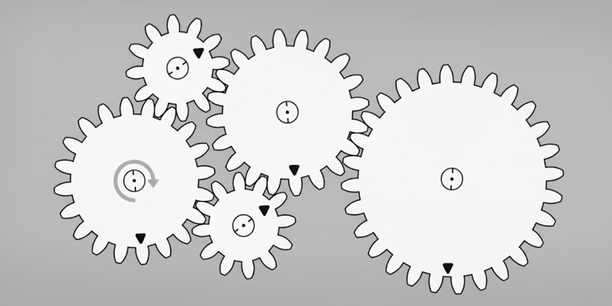
Beyond managing speed and force, gears expertly control direction.

Fig 4 Using an Idler Gear to Change Output Rotation Direction
Engineering Tip:
Keep in mind that while an Idler Gear reverses direction, it does not change the gear ratio.
However, every gear added introduces a small amount of friction.
Lily Bearing, we recommend using idler gears primarily for directional control or bridging gaps, but always account for a cumulative 1-2% efficiency drop per additional mesh.
Understanding the concepts of speed and torque is a start, but calculating them is where engineering begins. The Gear Ratio is critical.
The gear ratio is the defining number that predicts everything about a gear pair's behavior.
It's calculated as:
Gear Ratio = Number of Teeth on Driven Gear / Number of Teeth on Driver Gear
Let's use a real example. You have a 20-tooth motor pinion (driver) turning a 60-tooth gear (driven).
Calculation:
60 / 20 = 3:1
What this means:
This 3:1 ratio tells you:
This number is your first and most critical step in any drive design.

Fig 5 Calculation of Gear Ratios
These principles aren't abstract; they're the reason our machines work.
It uses helical and planetary gears to match driving needs.
It provides high torque (e.g., a 3.5:1 ratio in first gear) for starting and low torque (e.g., a 0.8:1 overdrive ratio) for highway cruising.
You are the engine, manually deciding when to trade pedal speed for hill-climbing torque.
It uses heavy speed reduction to turn a motor’s 1,725 RPM into a powerful 200 RPM for drilling through hardened steel.
This massive reduction is what generates the necessary torque to cut through metal without stalling the motor.
This system converts your steering wheel's rotation into the linear motion that turns your wheels.
For designers, the precision of the gear rack and its mating pinion is critical to achieving responsive, slop-free handling.
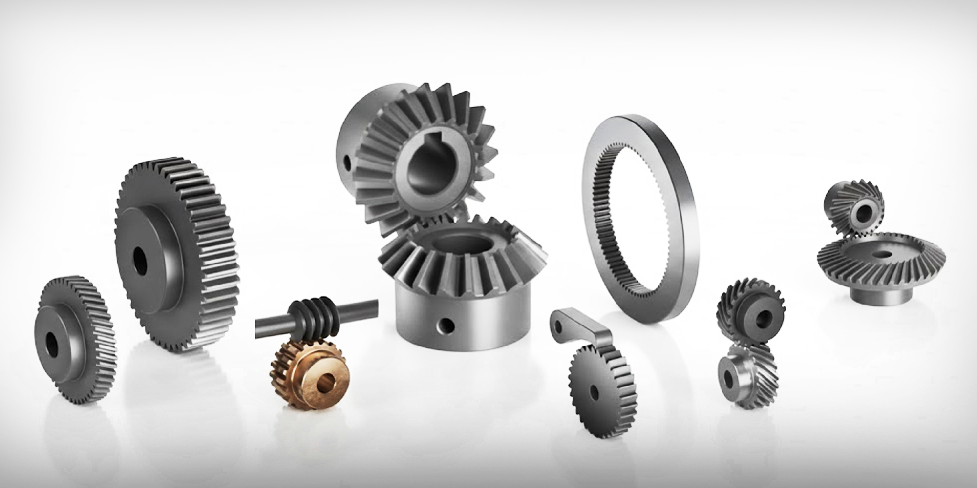
While the physics remain the same, the geometry determines the performance.
To help you choose, here is a quick comparison of the gears we provide at Lily Bearing:
Each type serves a specific purpose:
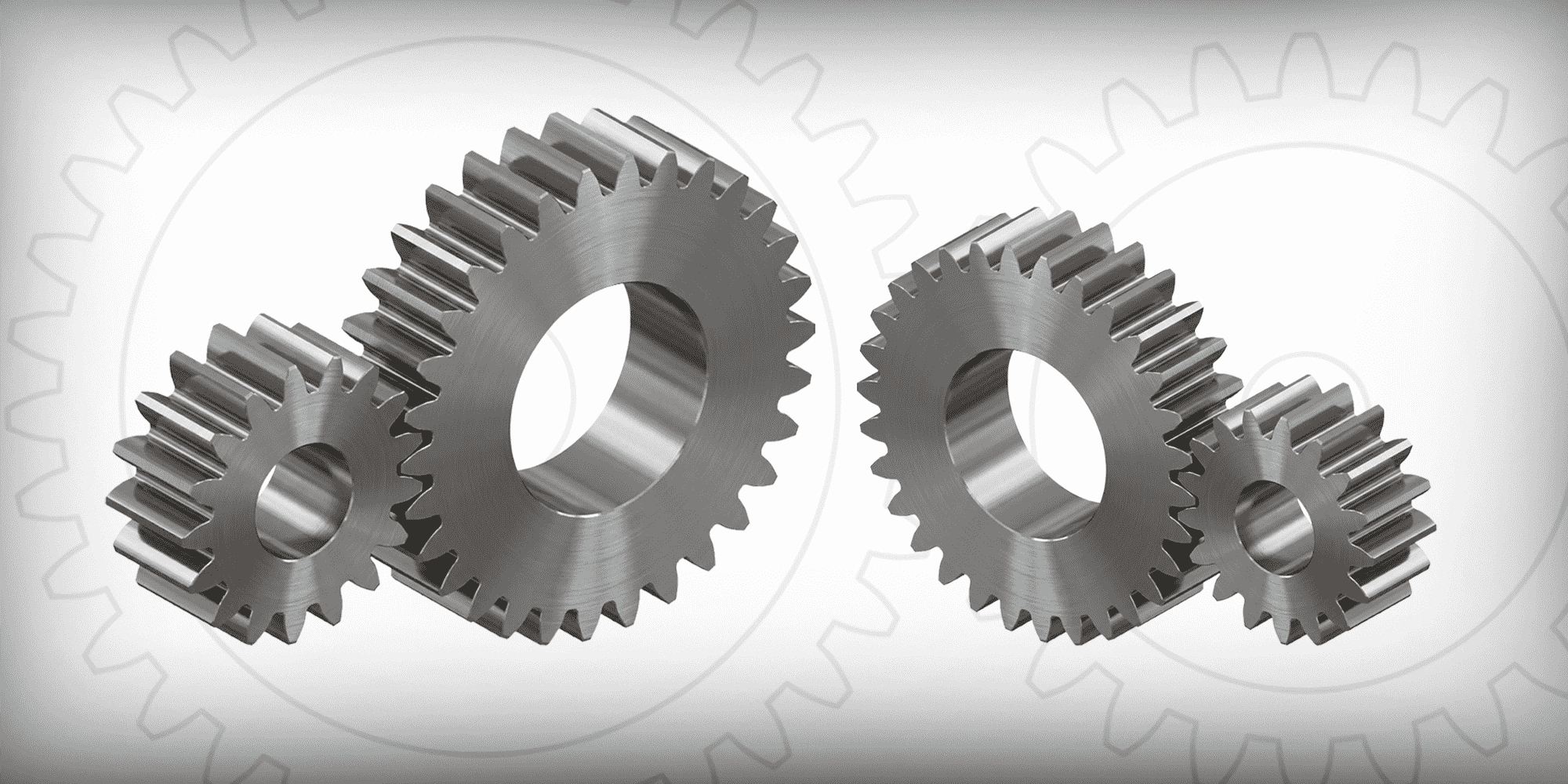
Most common and cost-effective type. They have straight teeth and are mounted on parallel shafts.
While they are highly efficient (up to 98%), their teeth engage all at once, which can create noise at high speeds.
In my experience, they are the "workhorse" for heavy-duty conveyors and low-speed machinery where simplicity is key.

These introduce angled teeth for quiet, smooth power transfer at high speeds.
Because the teeth engage gradually, they reduce vibration significantly compared to spur gears.
They are the preferred choice for automotive transmissions where noise reduction is critical.
Bevel & Miter Gears: Redirection Experts
These gears are designed to transfer power between intersecting shafts, typically at a 90-degree angle.


Design Tip: Miter gears are your best friend when space is tight and you only need a clean 90-turn without recalibrating your motor's RPM.
These provide massive speed reduction and can lock in place (self-locking).
This happens when the lead angle is small and friction is high enough to stop the worm wheel from turning the worm backward.
Note: Self-locking depends on the design; not all worm gears have this feature.

Choosing the right one is the art and science of mechanical design. Need to explore all gear options?
We cover everything from standard spur gears to custom planetary systems.
Check out our detailed guide: Types of Gears: An Engineer's Guide to Selection and Application.
Gears are more than just mechanical components. They are the logic of motion made physical.
By mastering speed-torque trade-offs and gear ratios, you can optimize any drive system for peak performance.
Ready to bring your design to life?
At Lily Bearing, we provide more than just parts—we provide engineering solutions. Whether you need standard Spur Gears or custom-engineered systems, our team is here to help you select the perfect fit for your application.
[Contact our Engineering Team] | [Browse Full Gear Catalog]
Walk into any factory, open up a household appliance, or look inside a medical device, and you'll almost certainly find a spur gear doing quiet,...
Gears remain fundamental components in mechanical systems worldwide, transferring motion and power between rotating shafts. Knowing which gear to...
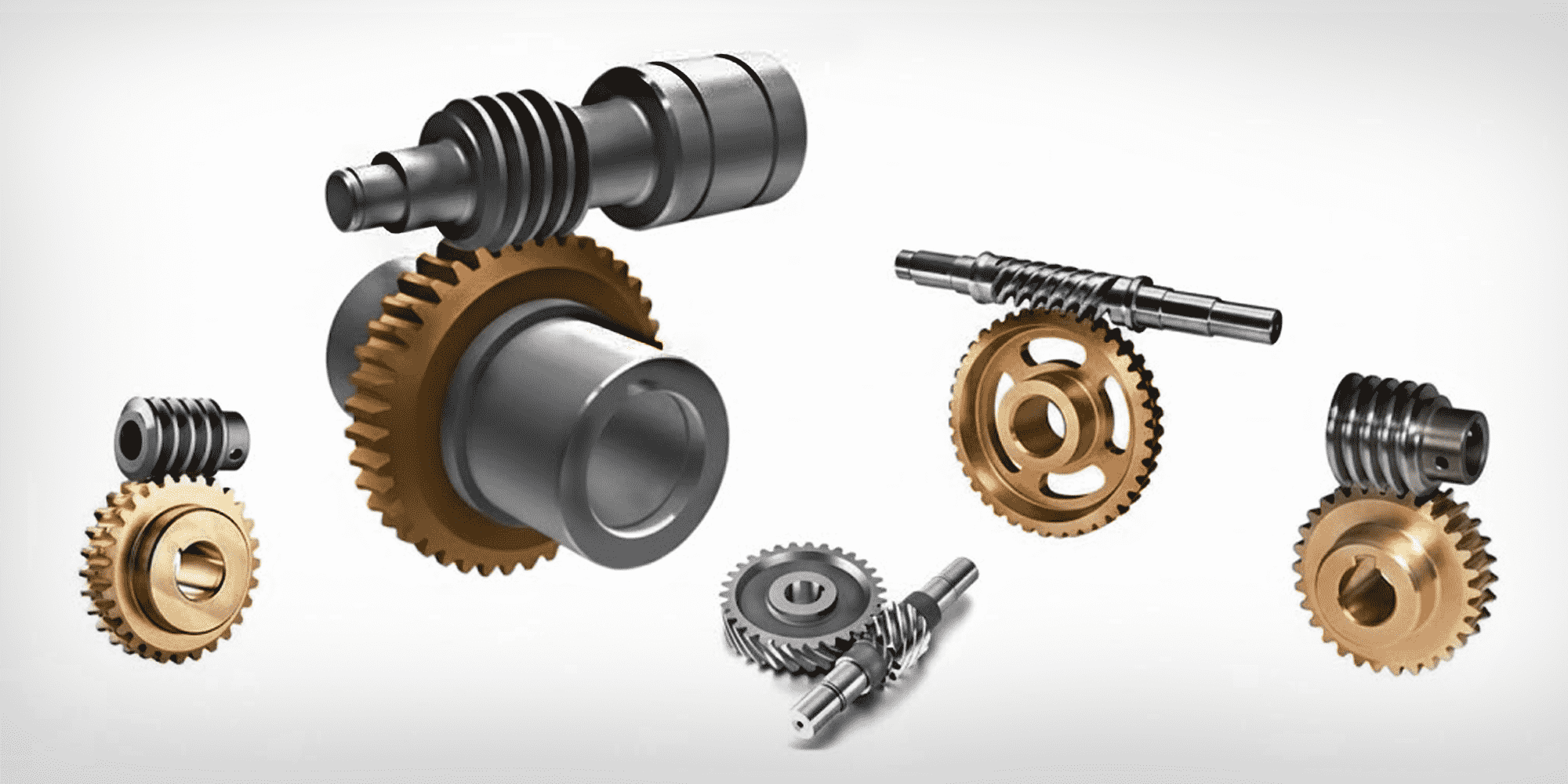
Worm gears are everywhere in daily life. You'll find them in car steering systems, conveyor belts, and stand mixers—often working invisibly behind...