

 Richard
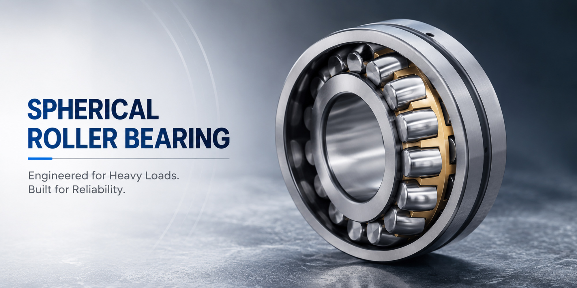
Spherical Roller Bearings in Wind Turbine Gearboxes: Challenges and Solutions
Introduction: Why Bearings Make or Break a Wind Turbine Wind energy has become one of the world's fastest-growing renewable energy sources, with...
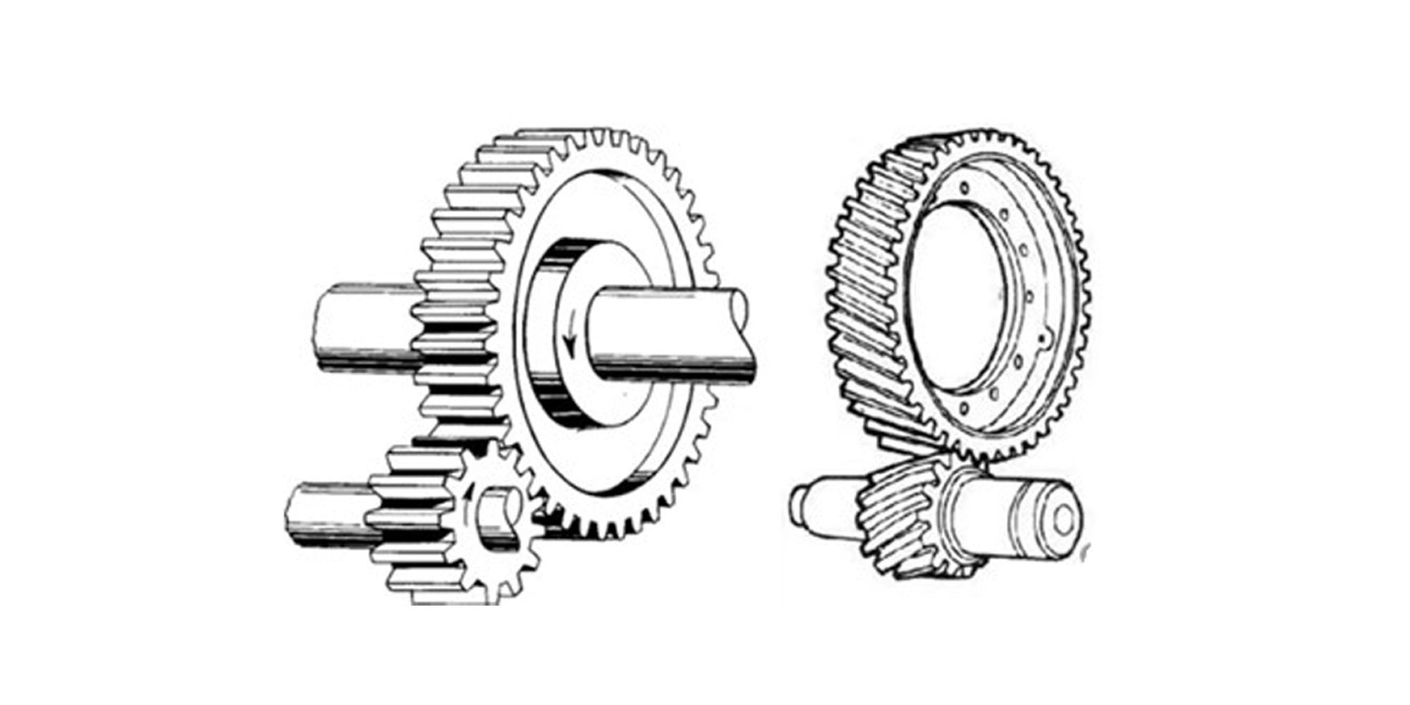
Transmission methods for equipment include mechanical, hydraulic, electric, and magnetic. Mechanical transmission is further divided into friction transmission (using belts, chains, etc.), mechanical transmission (couplings, universal joints, etc.) and gear mesh transmission (using gears).
Gear transmission is very common. To determine the bearing's rated service life and select the appropriate size and model of rolling bearings, it is crucial to consider the forces at the gear mesh point and the load transferred to the bearings.


Note:
Bearing A Radial Component Force
Bearing A Radial Resultant Force
Bearing B Radial Component Force
Bearing B Radial Resultant Force


Note:
The above bearing force analysis only considers forces from gear meshing. Even in systems without axial force, it is necessary to design locating and floating ends.
The use of cylindrical roller bearings at both ends of the gear shaft is shown for ease of understanding the theoretical absence of axial force in gear mesh transmission.
Introduction: Why Bearings Make or Break a Wind Turbine Wind energy has become one of the world's fastest-growing renewable energy sources, with...
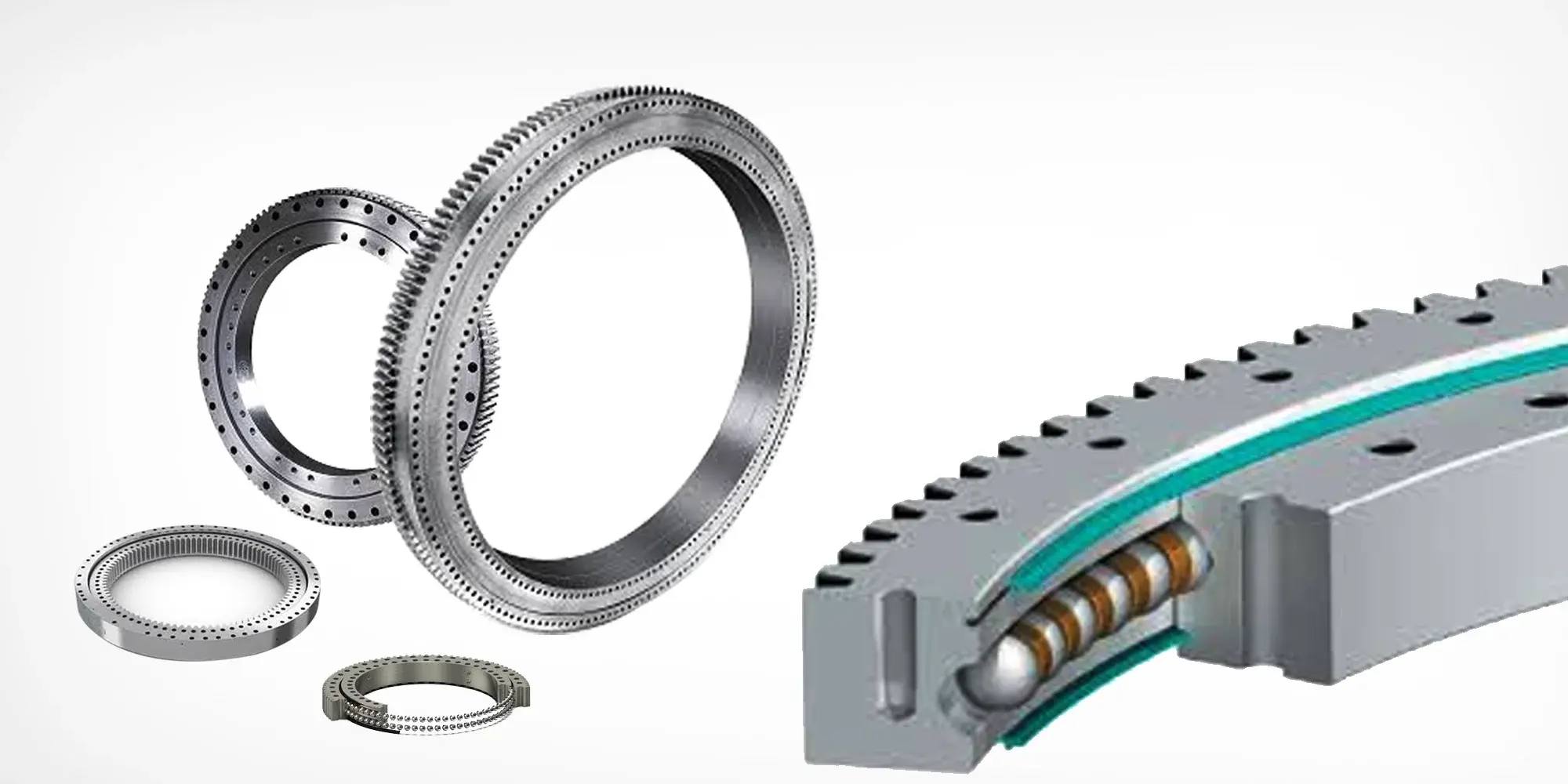
A slewing bearing failure on a mobile crane costs an average of $50,000–$200,000 in downtime and replacement — yet many engineers make their initial...
"Choosing the right bearing supplier isn't just about price — it's about finding a partner who can deliver consistent quality, technical support, and...