

 William
How Do Gears Work? A Guide to Speed, Torque, and Gear Ratios
Why do some mechanical systems prioritize raw power while others focus on high-speed rotation? At LILY Bearing, I’ve seen how a tiny adjustment in...
Straight bevel gears are low-cost and simple but limited to ~5 m/s pitch line velocity. Spiral bevel gears add a 25°–35° helix angle that raises load capacity by roughly 30–50% and cuts noise significantly. Hypoid gears offset the pinion axis entirely, enabling higher torque density and quieter operation at the cost of mandatory GL-5 EP lubrication. Which one fits your application comes down to five factors: shaft geometry, speed, power, noise budget, and lubrication logistics.
If you've ever opened a car differential, operated a hand drill, or designed an industrial gearbox, you've worked with bevel or hypoid gears — possibly without thinking too hard about which type you were using.
That distinction matters more than most engineers expect, especially once load cycles climb, noise budgets tighten, or shaft geometry gets constrained.
This guide breaks down the three most common designs — straight bevel, spiral bevel, and hypoid — across the dimensions that actually drive selection decisions: tooth geometry, load capacity, noise behavior, lubrication, and real-world fit.
Three Gear Types at a Glance
|
Straight Bevel Radial teeth, line contact, intersecting axes ≤ 5 m/s Max pitch line velocity 1.3–1.5 Contact ratio High Noise 500–2,000 Hz mesh frequency |
Spiral Bevel Curved teeth 25–35°, elliptical contact, intersecting axes ≤ 50 m/s Max pitch line velocity 2.0–2.5 Contact ratio Medium Noise 10–15 dB quieter than straight |
Hypoid Curved teeth, large elliptical contact, offset axes ≤ 50 m/s Max pitch line velocity 2.5–3.0+ Contact ratio Low Noise Quietest of the three |
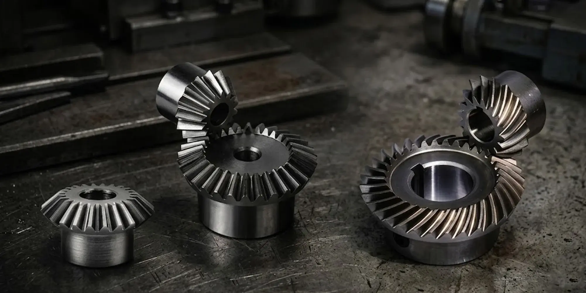
A bevel gear transmits rotational motion between two shafts whose axes intersect — almost always at 90°, though other angles are possible.
The teeth are cut on a conical surface rather than a cylinder, which is what distinguishes bevel gears from spur gears or helical gears.
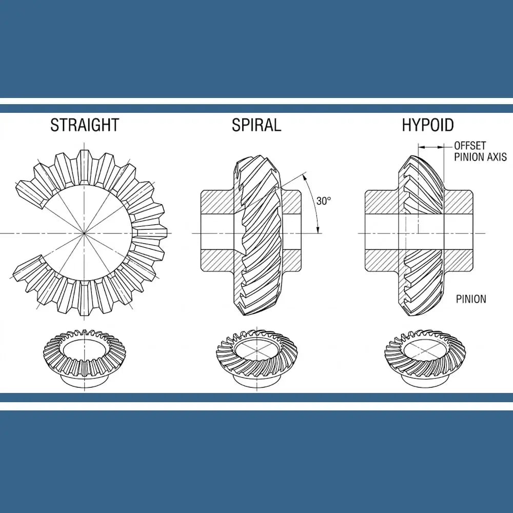
Cross-section drawings of straight bevel, spiral bevel, and hypoid gear sets. Note the radial teeth on the straight type, the 30° curved tooth helix on the spiral type, and the offset pinion axis on the hypoid — the pinion centerline sits below the ring gear centerline rather than intersecting it.
The defining geometric feature is the pitch cone: an imaginary cone whose apex sits at the shaft intersection point.
All tooth surfaces are generated relative to this cone.
When two bevel gears mesh, their pitch cones roll against each other without slipping — at least in theory.
In practice, tooth profile, helix angle, and shaft offset determine how closely reality matches that ideal.
One critical clarification: hypoid gears are not, strictly speaking, bevel gears. Their shafts do not intersect — the pinion axis is offset below (or above) the gear axis, typically by 25–40 mm in automotive rear axles.
This offset breaks the intersecting-axis geometry that defines bevel gears. Hypoid gears evolved from spiral bevel gears and are often grouped with them commercially, but they behave differently in ways that matter for engineering.
Straight bevel gear teeth are cut radially — each tooth points directly toward the pitch cone apex.
The tooth profile follows an involute (or octoid) curve, and there is no helix angle.
Contact begins and ends abruptly across the full tooth face width, typically 25–40% of the outer cone distance.
Because contact is essentially a line (not a surface patch), straight bevel gears carry lower loads per unit face width than their spiral or hypoid counterparts.
For a given module and face width, the contact stress is concentrated.
AGMA 2003-D19 geometry factors for straight bevel gears are consequently lower, which means you need a larger gear — or a harder material — to hit the same torque rating as a spiral bevel gear of equivalent size.
Practical pitch line velocities are generally limited to 5 m/s or less.
Above that threshold, the impact loading at tooth engagement becomes the governing failure mode rather than contact fatigue.
This is straight bevel's most significant limitation.
The abrupt, full-width tooth engagement produces an impulsive load that drives gear mesh frequency noise, often in the 500–2,000 Hz range depending on tooth count and speed.
At low speeds and light loads — hand tools, instrument drives, low-cycle indexing mechanisms — this is acceptable. In continuous-duty or high-speed applications, it is not.
Straight bevel gears remain the right choice when:
Typical uses: hand tools (drills, screwdrivers), printing presses, agricultural equipment auxiliary drives, right-angle gearboxes in light machinery.
Spiral bevel teeth are cut with a curved, oblique profile — the helix angle at the pitch circle is typically 25°–35°.
This means multiple teeth are always in contact simultaneously, and engagement is gradual rather than impulsive.
The contact pattern is an elliptical zone rather than a line.
The most widely used cutting system is the Gleason face-hobbing or face-milling process, which generates teeth on a circular arc.
Research published in the NASA Technical Reports Server on spiral bevel and hypoid gear tooth contact analysis confirms that this process produces a lapped gear set with a contact ratio substantially above 2.0, compared to 1.3–1.5 for straight bevel gears.
Higher contact ratio and a larger contact patch translate directly to higher load capacity.
For the same pitch, module, and material, a spiral bevel gear typically carries 30–50% more torque than an equivalent straight bevel gear before reaching the same bending or contact stress level — the exact margin varies with tooth geometry, precision grade, and material selection.
Pitch line velocities up to 25–50 m/s are achievable in precision-ground sets.
Axial thrust loads are significant — the helix angle that improves contact also generates a separating force along the pinion axis.
Bearing selection must account for this; tapered roller bearings are standard.
Gradual tooth engagement dramatically reduces the impulsive mesh excitation.
A well-lapped or ground spiral bevel set running at 1,500 rpm might generate 10–15 dB less gear mesh noise than a comparable straight bevel pair.
In automotive differentials and aircraft gearboxes, this is the reason spiral bevel gears replaced straight bevel gears as speed and power requirements increased through the 20th century.
Spiral bevel gears are the standard choice for:
Bevel vs Hypoid: Axis Relationship
|
Bevel Gear Axes intersect at a common apex |
Hypoid Gear Pinion axis offset — axes do not intersect |

A hypoid gear set looks similar to a spiral bevel set, but the pinion axis is offset — it does not pass through the gear axis.
This offset, called the hypoid offset or pinion offset, is typically expressed in millimeters or as a percentage of the gear outer diameter.
In a rear-wheel drive passenger car axle, the offset is commonly 25–40 mm, which allows the driveshaft to pass below the floor tunnel.
The offset changes the kinematics fundamentally.
Rolling contact — the dominant motion in bevel gears — is replaced by a combination of rolling and significant longitudinal sliding along the tooth face.
This sliding drives up friction and interface temperatures, and surface stress climbs compared to spiral bevel gears of similar size.
The trade-off: the contact ellipse grows larger and load spreads over more tooth area.
Hypoid gears carry more torque per unit size than spiral bevel gears.
The larger contact patch, combined with the ability to increase pinion tooth count without undercutting (because the pinion is smaller in diameter relative to the gear than in a bevel set), allows gear ratios of 3:1 to 10:1 with pinions that are structurally more robust.
A hypoid pinion for a 3,500 Nm rear axle application is typically 10–15% smaller in diameter than a spiral bevel pinion for the same duty.
Hypoid gears run quieter than spiral bevel gears in most passenger-vehicle applications.
The large contact zone and overlapping tooth engagement spread the mesh excitation over time and frequency, reducing tonal noise.
This is one reason virtually every rear-wheel-drive passenger car since the 1930s uses a hypoid rear axle: the combination of low floor height (from the pinion offset) and quiet operation is unmatched by any bevel gear design.
The longitudinal sliding that gives hypoid gears their load capacity also generates severe contact conditions — film thicknesses drop and interface temperatures rise compared to rolling-dominant bevel contact.
Standard gear oils are inadequate.
As documented in NASA's gear lubrication reference literature, hypoid gears require GL-5 rated gear oil containing extreme-pressure (EP) additives, typically sulfur-phosphorus chemistry.
Using the wrong lubricant in a hypoid axle accelerates surface fatigue — pitting and scoring follow quickly, often within tens of thousands of kilometers.
This is not an optional precaution — it is a design constraint.
Contact Ratio Comparison
|
Straight Bevel |
|
|
Spiral Bevel |
|
|
Hypoid |
|
Higher contact ratio = more teeth sharing load simultaneously = lower stress per tooth
Relative Noise Level
|
Straight Bevel |
High — 500–2,000 Hz mesh excitation |
|
Spiral Bevel |
Medium — ~10–15 dB quieter than straight |
|
Hypoid |
Low — quietest of the three |
| Parameter | Straight Bevel | Spiral Bevel | Hypoid |
|---|---|---|---|
| Shaft axes | Intersecting | Intersecting | Offset (non-intersecting) |
| Helix angle | 0° | 25°–35° | 25°–35° (approx.) |
| Contact type | Line | Elliptical patch | Large elliptical patch |
| Contact ratio | 1.3–1.5 | 2.0–2.5 | 2.5–3.0+ |
| Max pitch line velocity | ~5 m/s | ~50 m/s | ~50 m/s |
| Load capacity | Low | Medium–High | High |
| Noise level | High | Medium | Low |
| Lubrication | Standard gear oil | Standard gear oil | EP GL-5 required |
| Gear ratio range | 1:1–6:1 | 1:1–8:1 | 3:1–10:1 |
| Manufacturing complexity | Low | Medium–High | High |
| Axial thrust loads | Moderate | Significant | Significant |
Selection Decision Flow
|
START: Define your constraints
|
||||||||||
|
|
||||||||||
|
Shafts must be offset?
|
||||||||||
|
If your shafts must be offset — either for packaging reasons or to lower the output shaft centerline — hypoid is your only practical option among these three.
If pitch line velocity exceeds 5 m/s or power exceeds roughly 5–10 kW in continuous duty, straight bevel is off the table.
The impulsive loading and limited contact ratio will produce noise and vibration levels that accelerate fatigue failure.
Passenger-vehicle and consumer-appliance applications almost always end up at spiral bevel or hypoid.
Industrial gearboxes in pump houses or open-air installations may tolerate straight bevel noise levels.
If you cannot guarantee GL-5 EP oil in service — remote equipment, user-maintained systems, low-maintenance environments — hypoid gears carry operational risk.
Spiral bevel gears run on standard industrial gear oil and are more tolerant of lubrication variation.
Straight bevel gears can be cut on relatively simple gear-cutting equipment.
Spiral bevel and hypoid gears require specialized Gleason or Klingelnberg machines and often lapping or grinding.
For low-volume or cost-sensitive applications, the manufacturing premium matters.
Not strictly. Bevel gears are defined by intersecting shaft axes.
Hypoid gears have offset axes, which changes their kinematics and lubrication requirements.
They are closely related — hypoid cutting uses the same Gleason-type machines as spiral bevel gears — but they are geometrically distinct.
The pinion offset in hypoid gears introduces longitudinal sliding across the tooth face during mesh.
This sliding is much more severe than in spiral bevel gears, where contact is dominated by rolling.
The higher sliding velocity and pressure require EP additives to prevent metal-to-metal contact and scoring.
Yes — and this comes up more often than you'd think in conveyor reversals and winch drives.
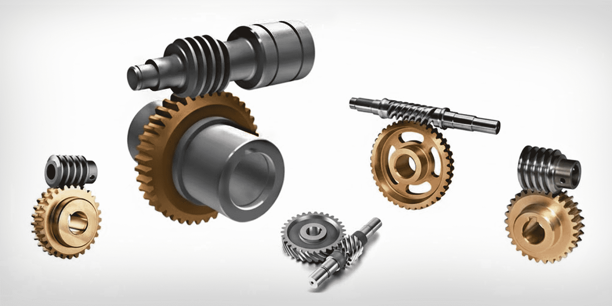
Unlike worm gears, which can self-lock and resist back-driving, bevel gears transmit power equally in either direction.
The same is true for spiral bevel and hypoid types, though on hypoid sets the efficiency difference between forward and reverse is measurable (typically 1–3 percentage points) because the longitudinal sliding direction reverses relative to the tooth crown.
The helix angle on the teeth produces a force component along the pinion and gear axes when torque is transmitted.
The direction of this thrust depends on the hand of spiral (left or right) and the direction of rotation.
Bearing arrangements must be designed to handle this thrust — tapered roller or angular contact bearings are standard.
A Zerol bevel gear has curved teeth like a spiral bevel gear but with a zero helix angle at the midface.
It was developed by Gleason to allow spiral bevel manufacturing equipment to produce gears that can replace straight bevel gears in existing housings without redesigning bearing arrangements, since Zerol gears generate lower axial thrust than spiral bevel gears.
They are less common today but appear in aerospace accessories and instrument drives.
Straight bevel gears are simple, inexpensive, and well-suited to low-speed, low-power, or intermittent applications.
Once speed or load climbs, spiral bevel gears offer dramatically better noise and load performance.
Hypoid gears extend spiral bevel capability further — the offset pinion axis enables lower floor heights and driveshaft routing that a bevel gear simply can't match, while load density goes up and noise goes down — at the cost of stricter lubrication requirements and higher manufacturing complexity.
The choice between them is rarely ambiguous once shaft geometry, speed, power, noise, and lubrication constraints are on the table.
If you're selecting gears for a new design, work through those five parameters in order and the right answer usually becomes clear.
Need Bevel or Hypoid Gears?
LILY Bearing supplies straight bevel, spiral bevel, and hypoid bevel gears across metric and inch standards, with material options including case-hardened alloy steel, stainless steel, and engineering plastics.
Browse Bevel Gear Catalog →
Why do some mechanical systems prioritize raw power while others focus on high-speed rotation? At LILY Bearing, I’ve seen how a tiny adjustment in...
Worm gears are everywhere in daily life. You'll find them in car steering systems, conveyor belts, and stand mixers—often working invisibly behind...
Walk into any factory, open up a household appliance, or look inside a medical device, and you'll almost certainly find a spur gear doing quiet,...